Fabricated Upper Ignition Wire Supports

I fabricated a couple of supports for the upper ignition wires.  I’ll probably drill a couple of lightening holes to shave off a little weight.

The spark plug wire supports screw to the upper flange of the support.

Here’s where they will be installed.  They’re clamped to the inner push rod tubes with a couple of adel clamps.

After installing both and adding some Tefzel zip-ties, the wires are really nicely supported and spaced apart.

The wires arc up slightly from the coils and curve over the fuel spider.  There’s over 1/2″ of clearance and the wires have to be pushed down pretty firmly to deflect anywhere near the spider.

Hooked up Electronic Ignition

I cut the high-tension leads down and installed the fast-on connectors.  You can see that I used some large rubber grommets that allow me to pull the fast-on connectors through the baffles so I can remove them.

After that, I fired up the ignition and phased the coils.  The left one (right in this picture) fires the #1 and #2 cylinders, and the right one fires the #3 and #4 cylinders.

I added a couple of zip ties to the high tension leads so that they won’t rub on the engine mount.  You can see that there is some slack in these lines to allow for engine movement.

Sealed Firewall Pass-Throughs

I’m done running wires through the firewall (I hope), so I sealed up the pass-throughs.  The wires are wrapped tightly with some silicone impregnated fiberglass and then wrapped that with silicone tape.  The silicone impregnated fiberglass sleeve is then slid over the whole mess and squeezed tight with the worm clamps.  The back one tightens against the flange and the front one tightens against the wires.  This is the one on the right side of the firewall.

And here’s the one on the left side of the firewall.

Misc Firewall Forward Work

I fabricated a little standoff to anchor the alt air cable at the aft end of the baffles.  It’s just a short piece of 0.063″ aluminum with a nutplate riveted to the back.  It has a hole in the other end and is installed behind the upper adel clamp.

Here you can see that this keeps the cable well clear of the EGT probe as well as the wire bundle above.

I also rerouted the manifold pressure wires to run along the firewall instead of directly out to the engine mount.  They’re better supported now and less likely to get snagged while working on the plane.

The tube going to the Dynon manifold pressure sensor was a little loose (although it was tight when I originally installed it).  I used a couple of wraps of safety wire to tighten this up nicely.

To space the wingtip hinges away from the skin, I need a couple of 0.024″ spacers under each hinge.  I cut a few of these by hand, but that was a real pain and it really twisted them up.  I recently got a lifetime membership to the TechShop, so I ran down there and used their shear to cut 6 more 1/2″ wide strips.  Even counting the drive, this was way faster than doing this with snips (not to mention how much easier it was on my hands).

While I was there, I cut some 1.5″ wide strips of 0.040″ and bend them to 90º on the bending brake.  These will be installed on the baffles to provide a mounting flange for the plenum over the engine.

Hooked up Alternate Air Cable

I hooked up the alt air cable tonight.  The cable is anchored to the oil return lines on both cylinders #2 and #4.  I will have to replace the white silicone adel clamps with standard black rubber ones because the silicone ones can move around a little, but all this has to come apart when the panel is pulled out of the plane for painting/ labeling.  You can also see that the aft end of the visible cable dips down and comes very close to the EGT probe.  I’ll probably fashion a small bracket to keep the cable going straight back until aft of the baffles.

With the cable pulled all the way back, you can see how the door opens.  The door rubs on the #2 cylinder oil return line while opening, but this will only be opened in an emergency and during the annual inspection, so it will not be an issue.

Ran Oil Cooler Valve and Alt Air Cables

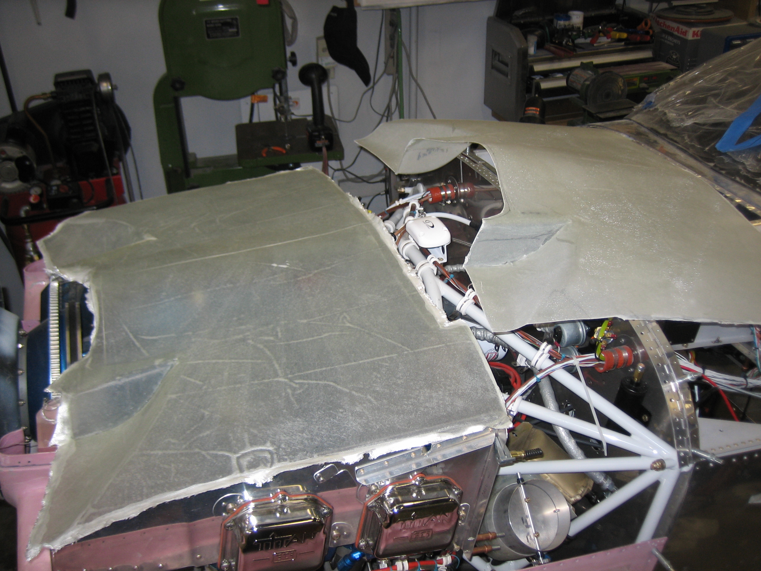
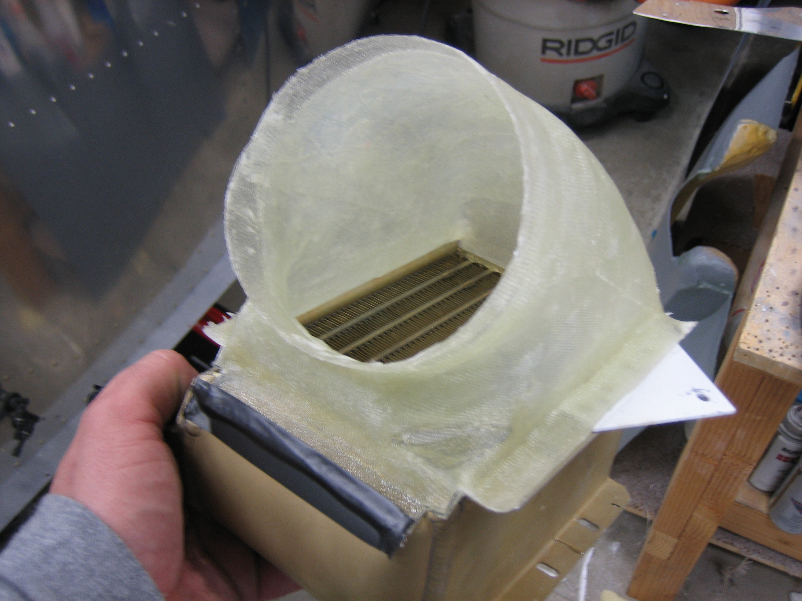
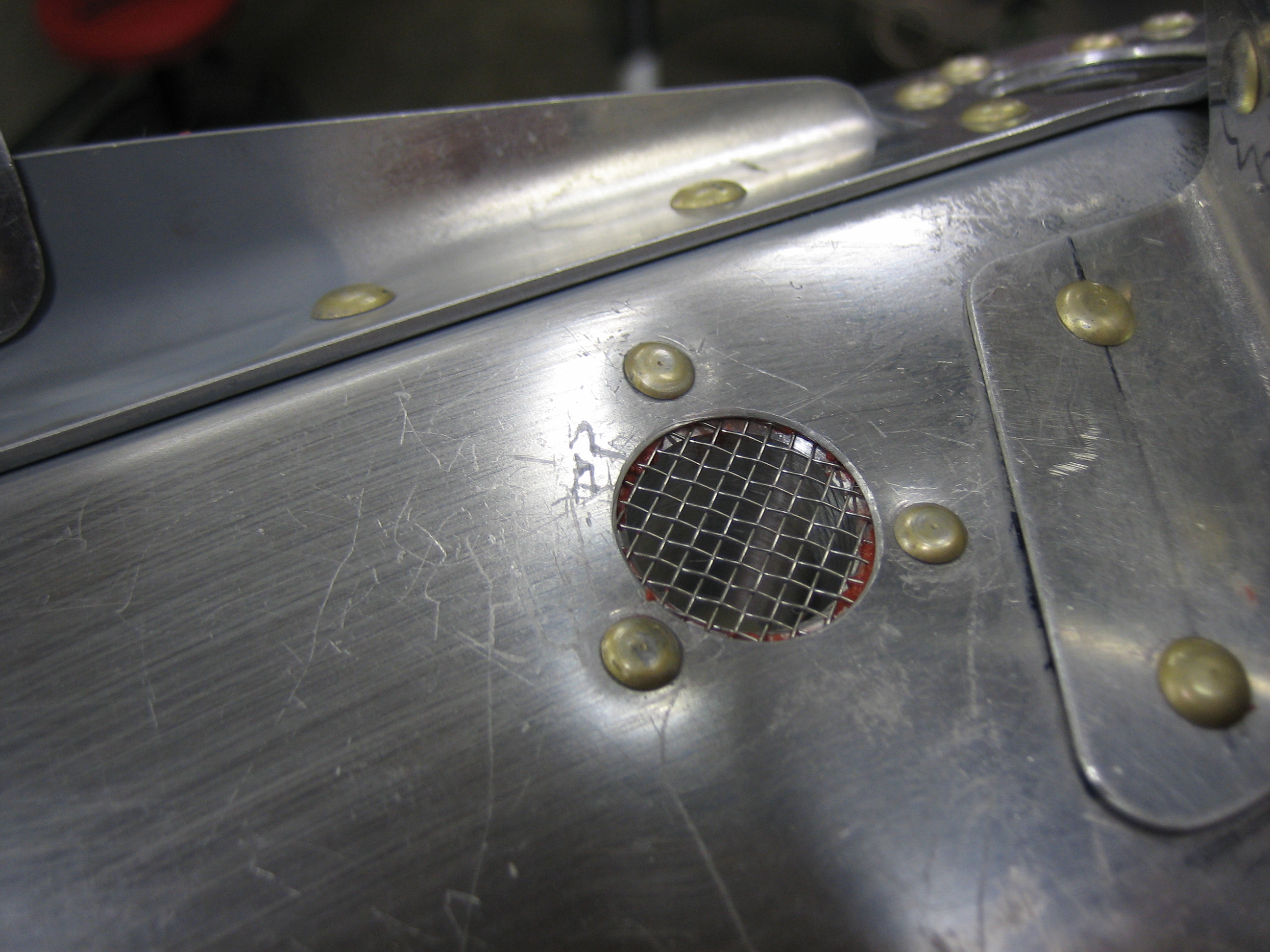
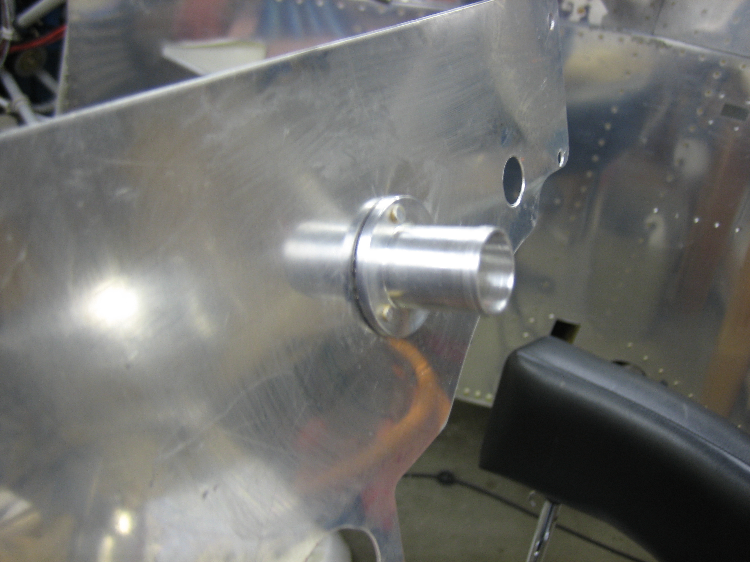
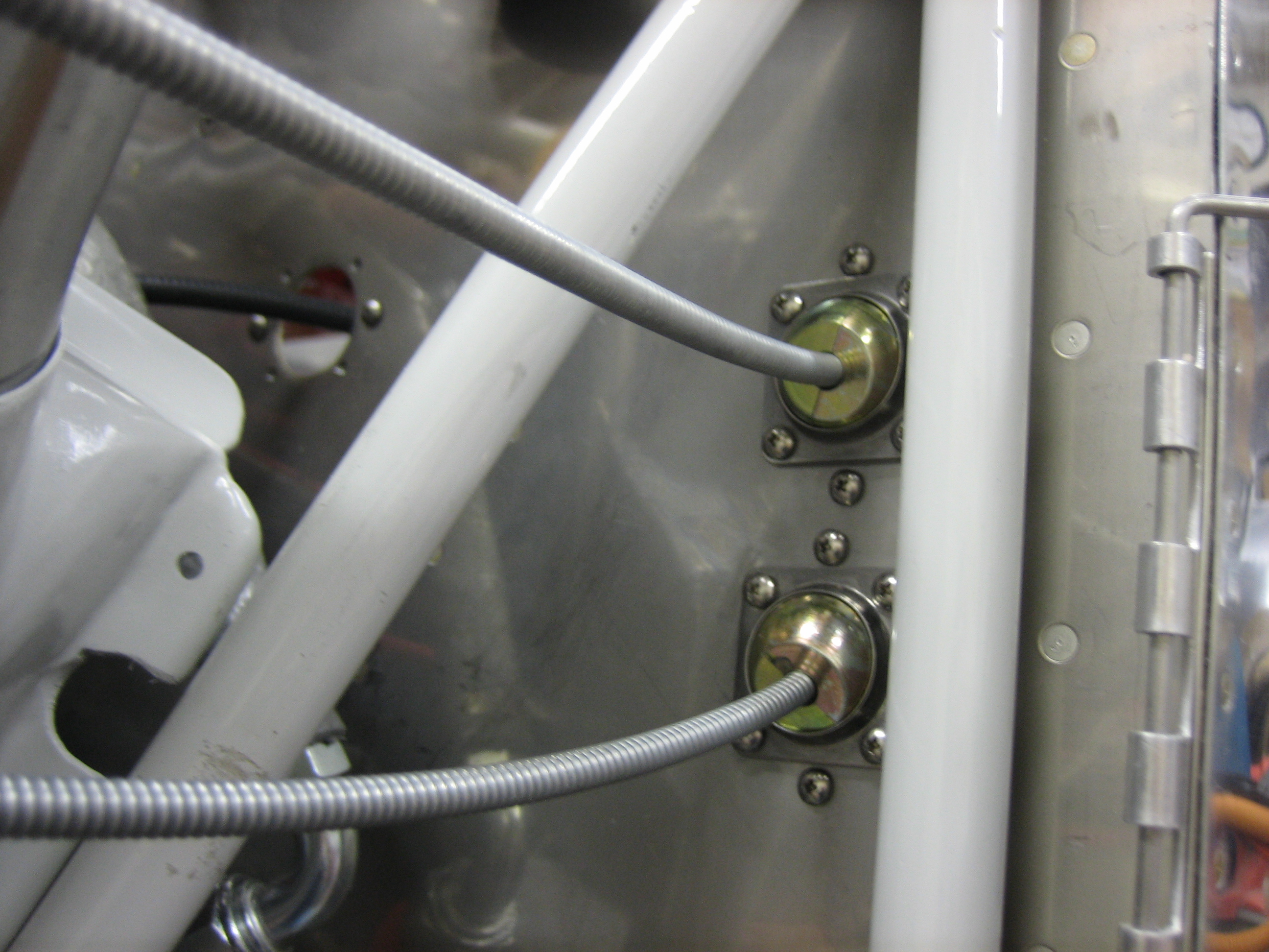
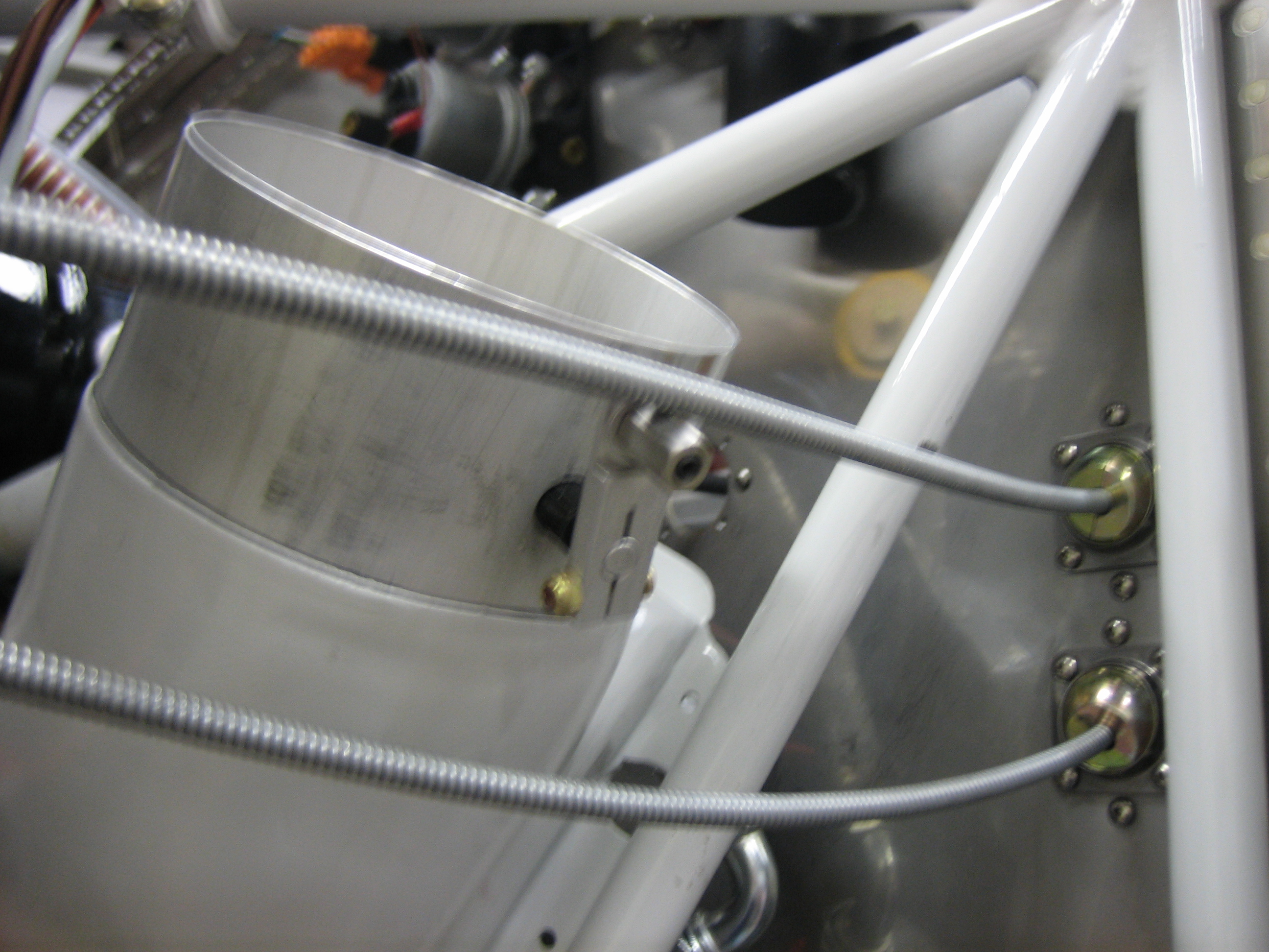
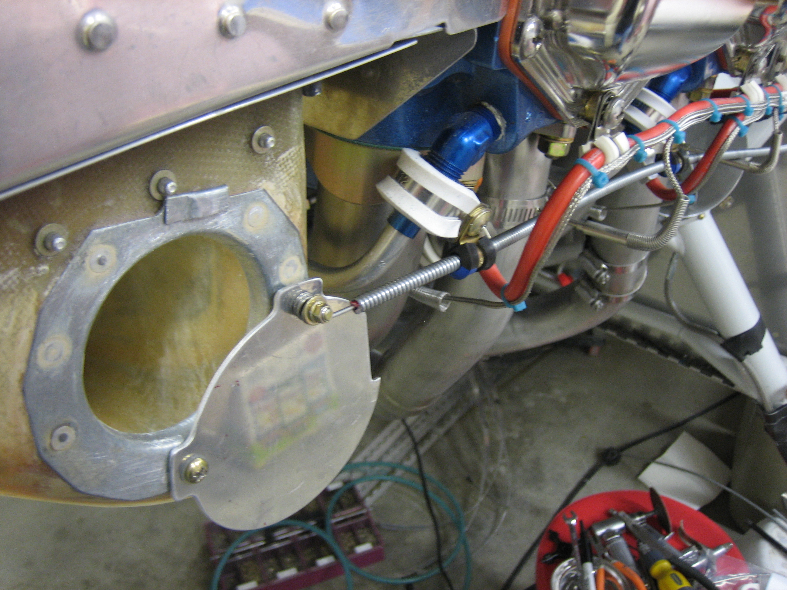
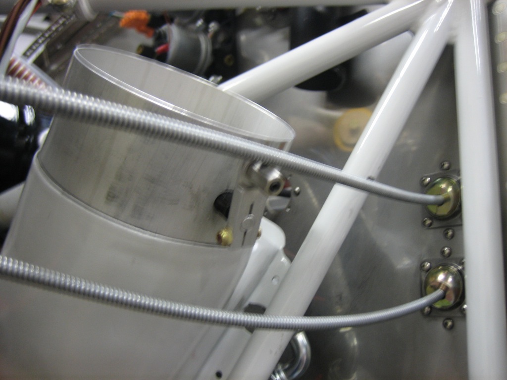
I drilled two additional holes in the firewall for the eyeball pass-throughs.  The top hole is for the cable that will control the oil cooler butterfly valve.  The lower hole is for the cable that will open the alt air port.

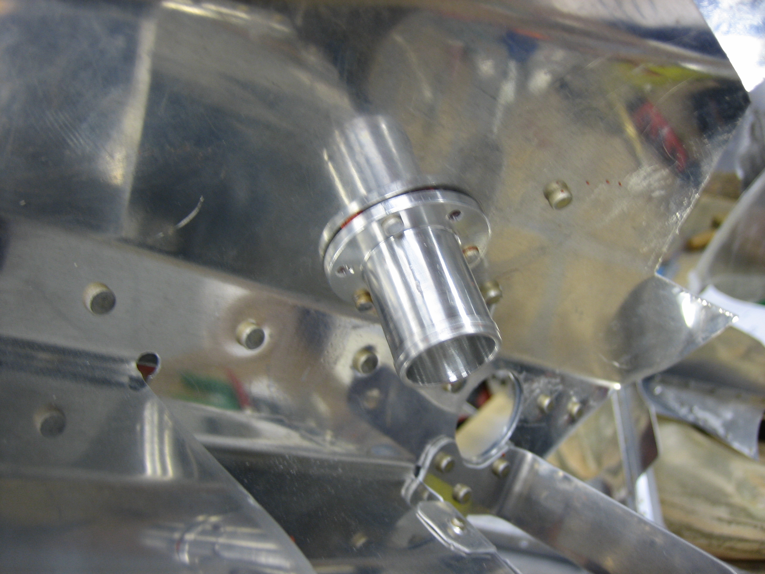
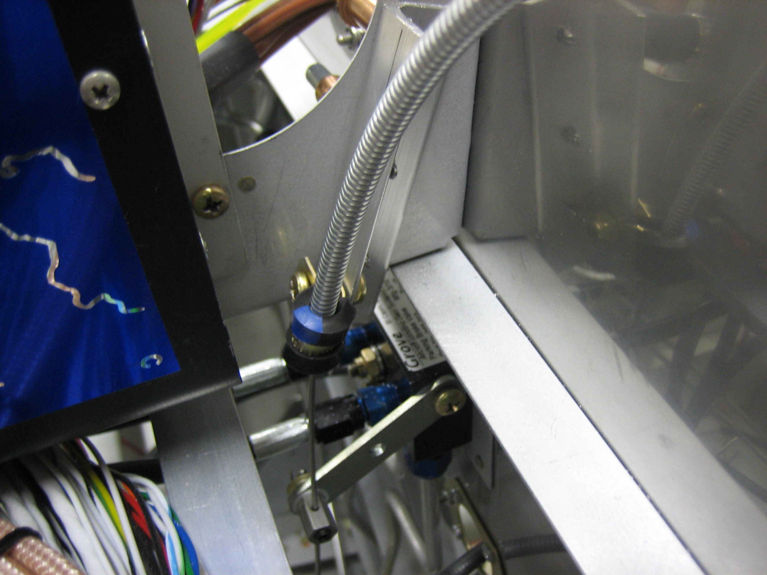
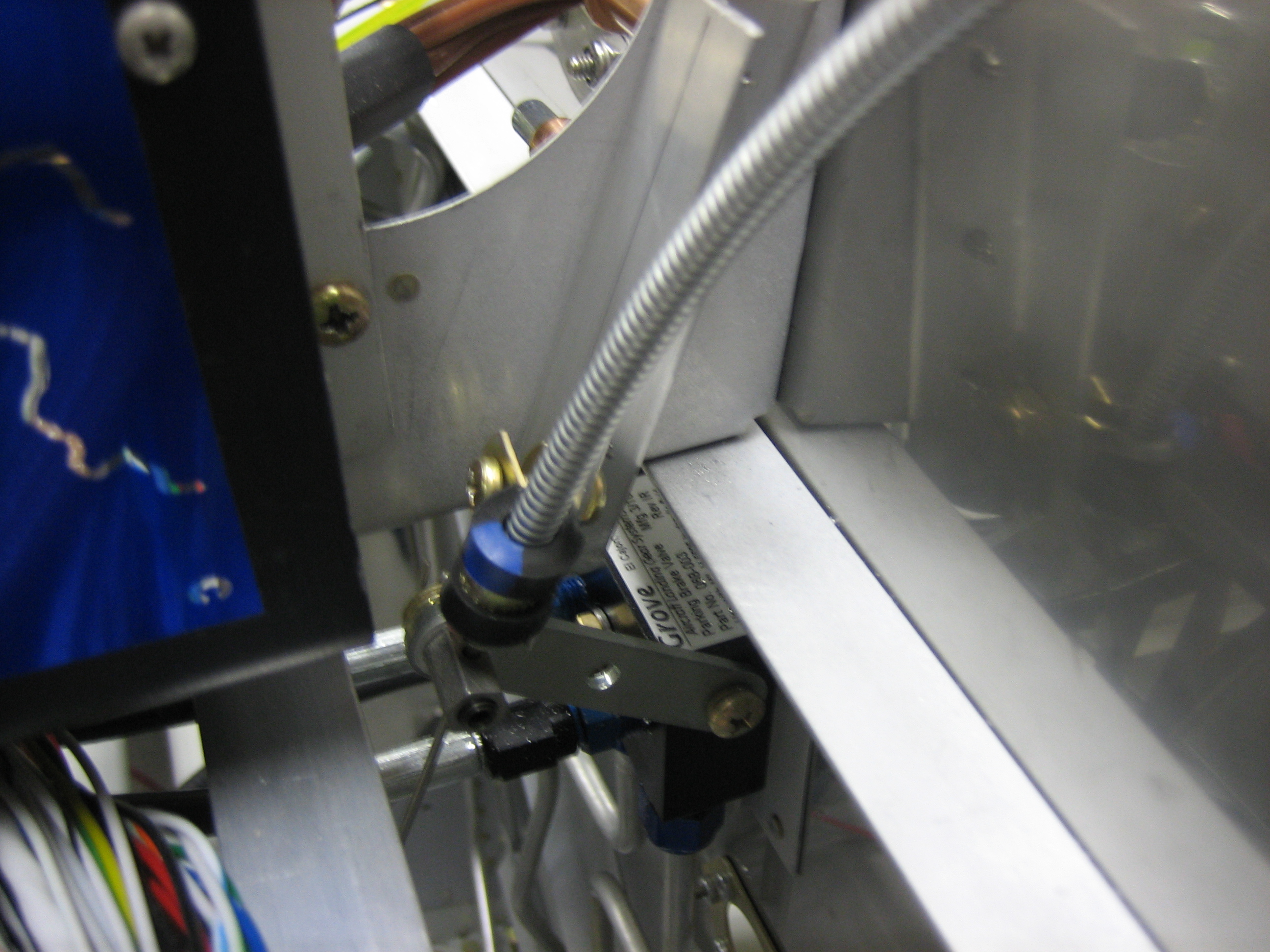
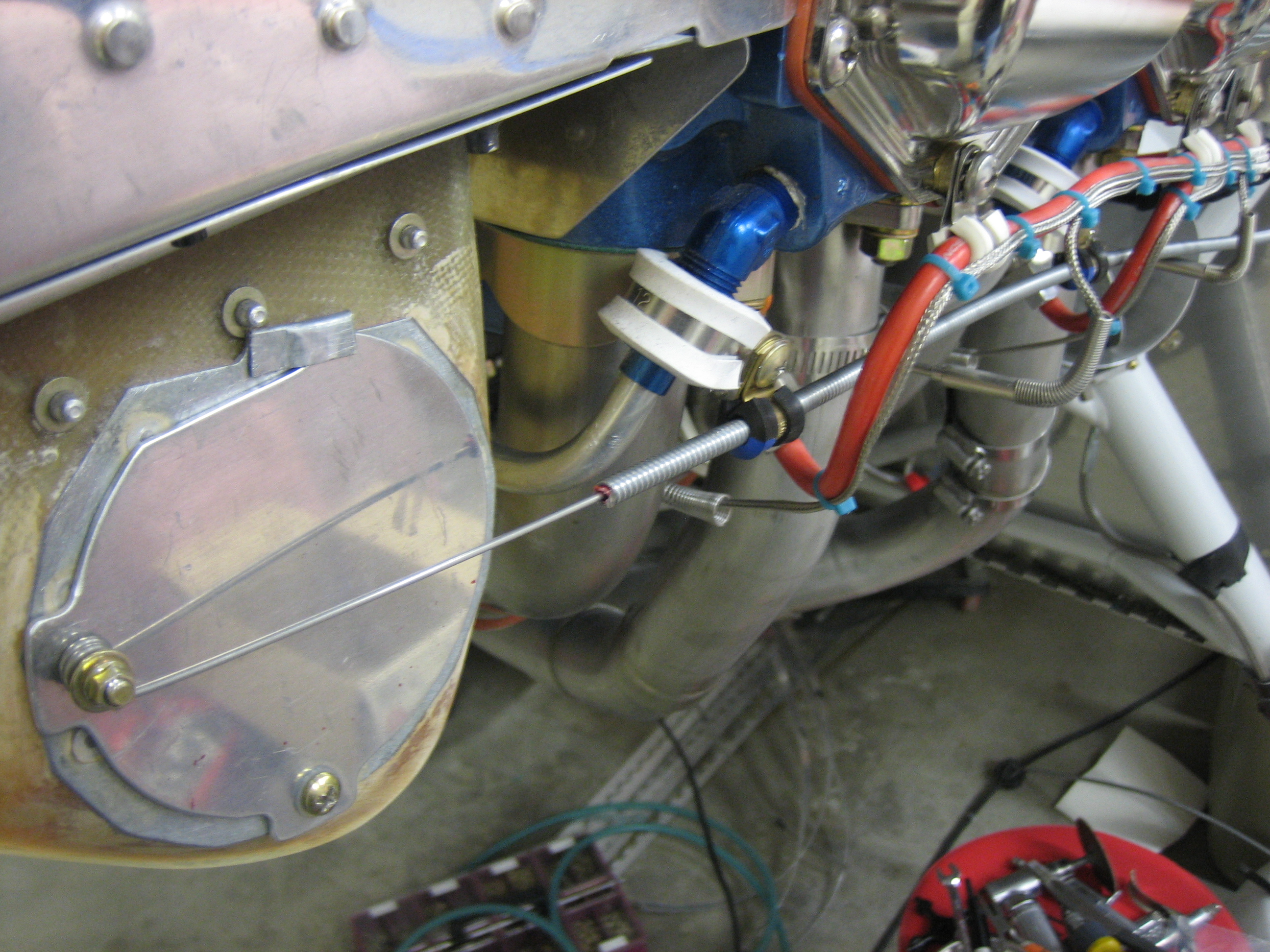
It’s pretty much a straight shot from the upper hole to the arm that will operate the butterfly valve (especially after I adjust the angle of the eyeball).  I’m a little disappointed in these butterfly valve though.  Aircraft Spruce specified this hole size for these cables, but the holes are a little oversized (they should be a few thousandths undersized so they securely clamp the cable).  I’ll have to wrap some aluminum tape around the cable to tighten up the fit.

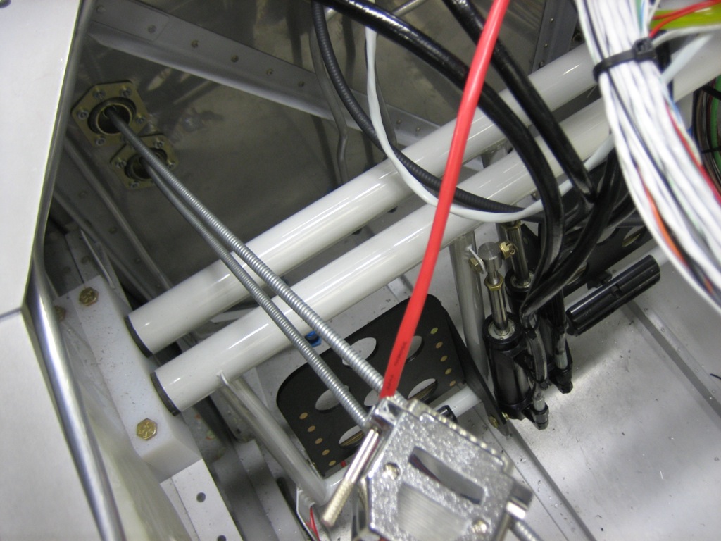
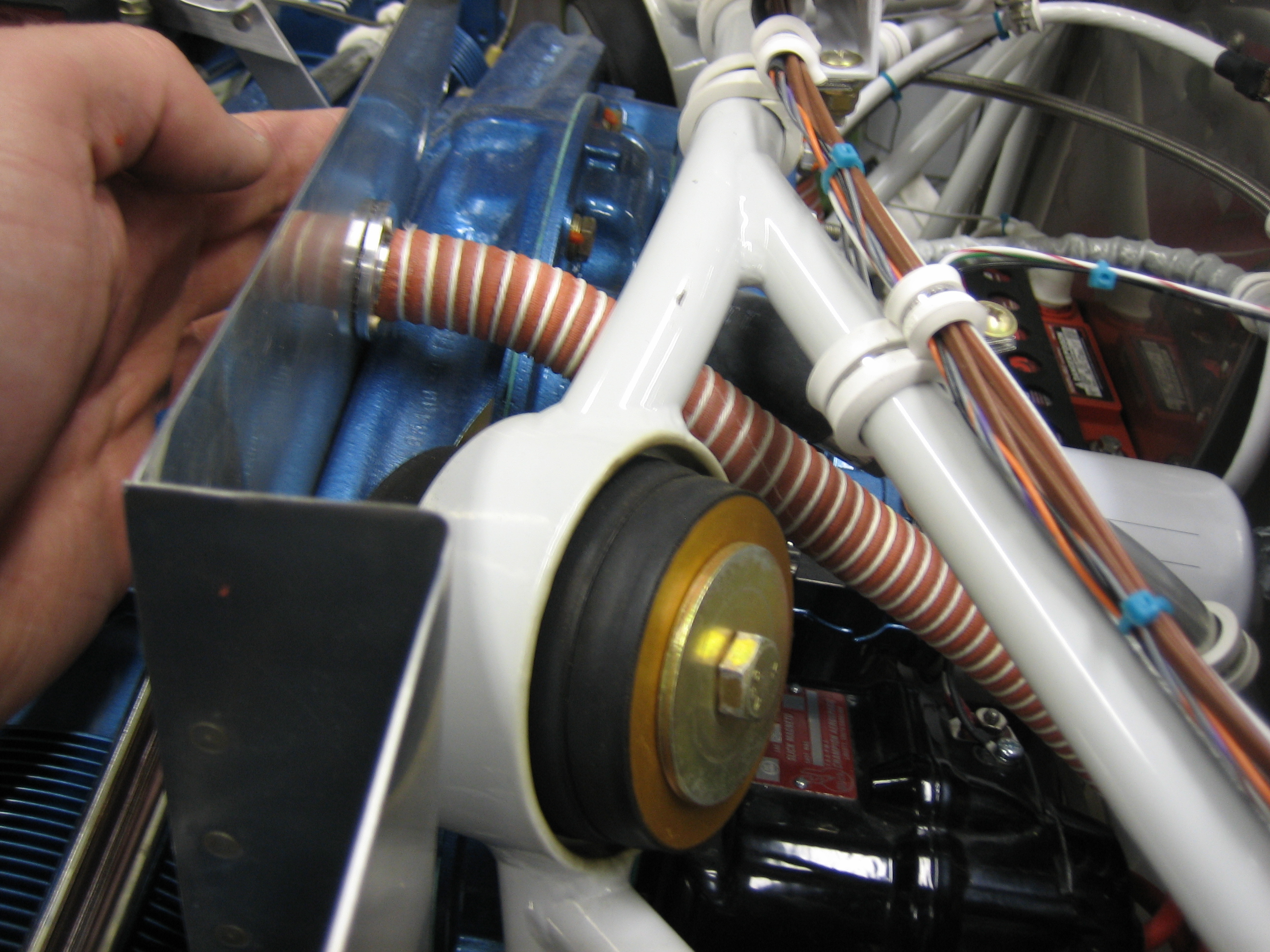
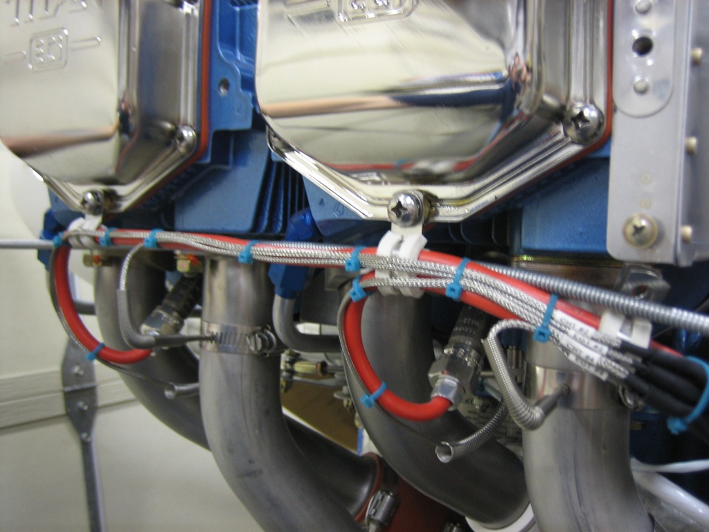
The lower cable will route behind the spark plug wires and be clamped to the oil return fittings.

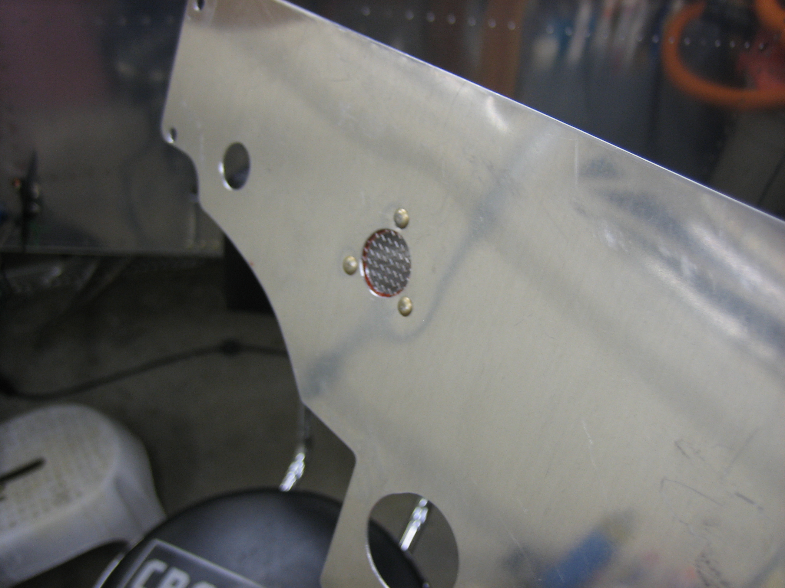
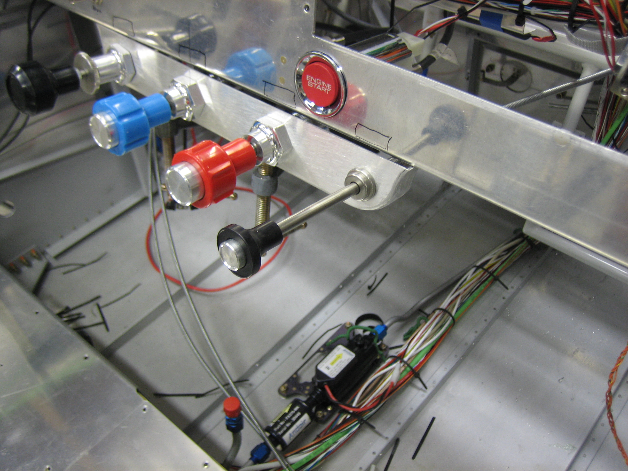
On the other side of the firewall, it’s pretty much a straight shot from the panel to these holes.  They’ll be anchored to the bottom of the subpanel and tied together in the middle.  It looks like they’re about to touch the rudder pedal bars, but there will be roughly 1″ of clearance once everything is anchored.

Installed Parking Brake Cable

I installed the parking brake cable tonight.  The cable comes pretty much straight back from the panel and then turns up and is anchored to one of the angles that support the VP-X (seen in the lower right of the photo).  The cable then arcs across the cabin (anchored in the middle to forward top skin center rib).

The cable is then anchored to a piece of 0.063″ angle that is attached to the left subpanel rib.  The angle serves as a mounting point for the cable as well as a stop for the parking brake arm.  Here is the parking brake with the cable full forward which is the off position.

Here is the parking brake on the on position.

Here is how far out the parking brake knob comes with the parking brake on.

Painted Oil Cooler Plenum

I put a couple of coats of paint on the oil cooler plenum.  This is Cardinal Paint gloss gray that exactly matches the powder coat used on the engine mount.  There are still some minor surface imperfections, so I may sand and reshoot one more time.

Final Shaping of Oil Cooler Plenum

I trimmed the excess epoxy/flox mixture from the edges of the flanges and made the intake square to the opening and flat.

The flox mixture allowed the flanges to fit perfectly over the flange extension.

And filled in nicely where the flanges end.  There will be some high-temp RTV between the mounting surfaces to seal any small openings.

I mixed up some epoxy with lightweight filler and buttered up the surface to smooth it out.  This should be cured enough to sand by tomorrow.