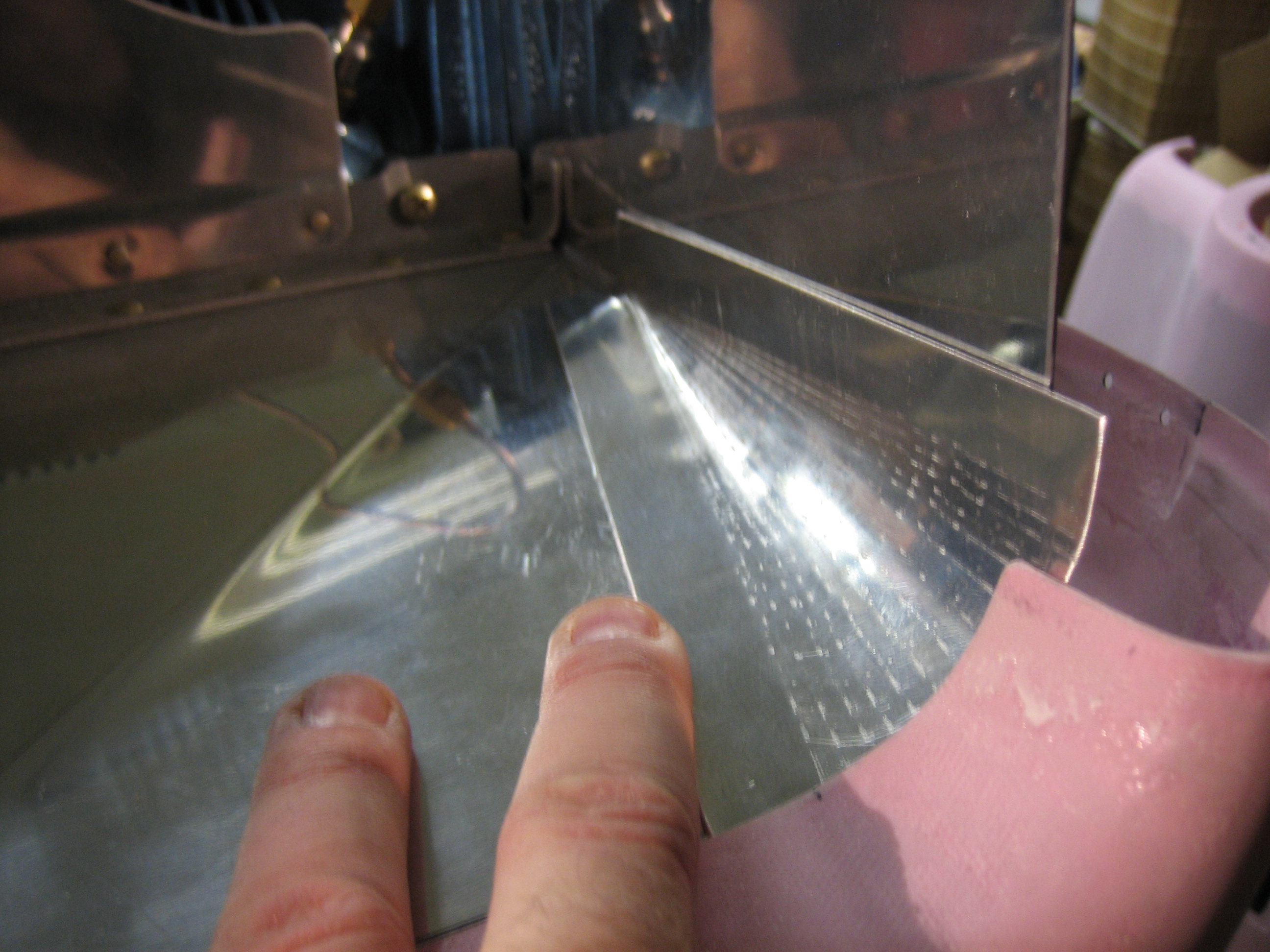
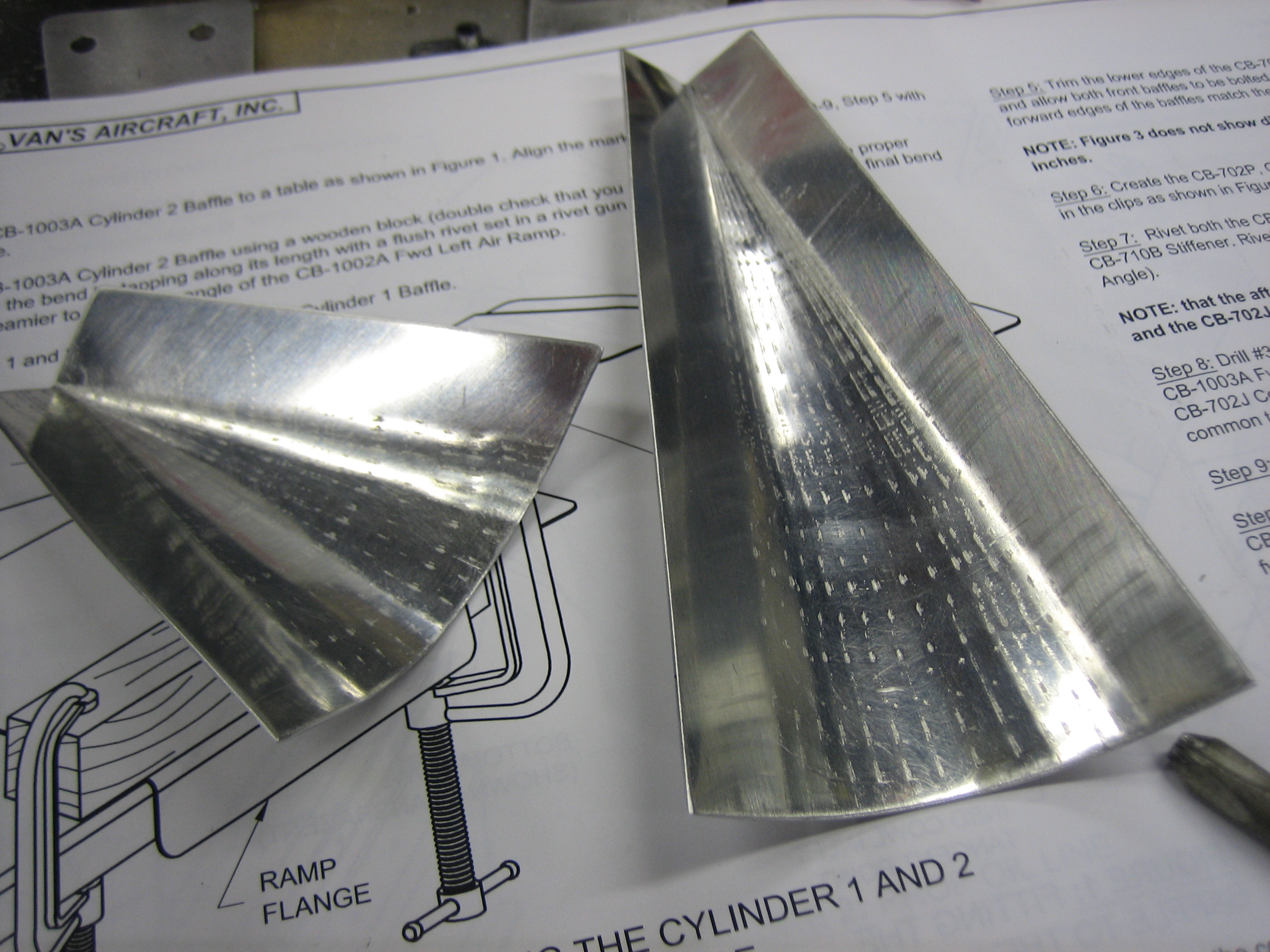
I formed the left conical gusset this afternoon. This creates a curved surface for the cowl inlet seal material to lay against. Since the cowl inlet is curved, this provides a smooth transition for the airflow.

I formed the left conical gusset this afternoon. This creates a curved surface for the cowl inlet seal material to lay against. Since the cowl inlet is curved, this provides a smooth transition for the airflow.
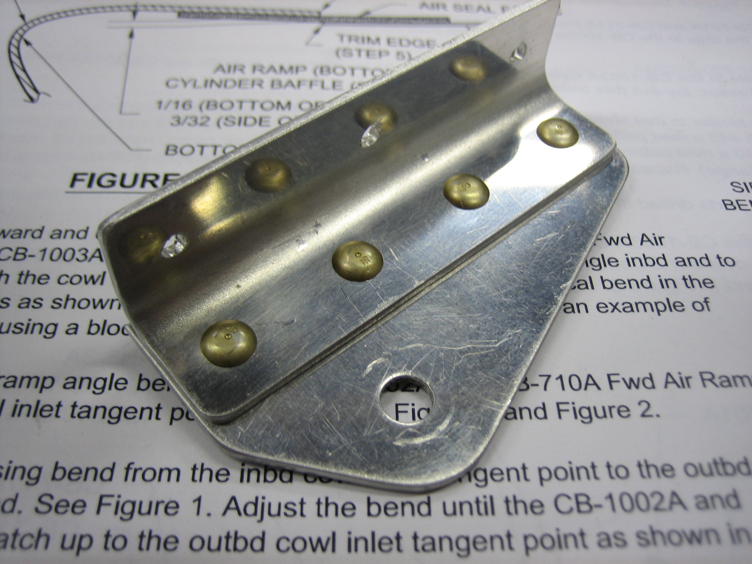
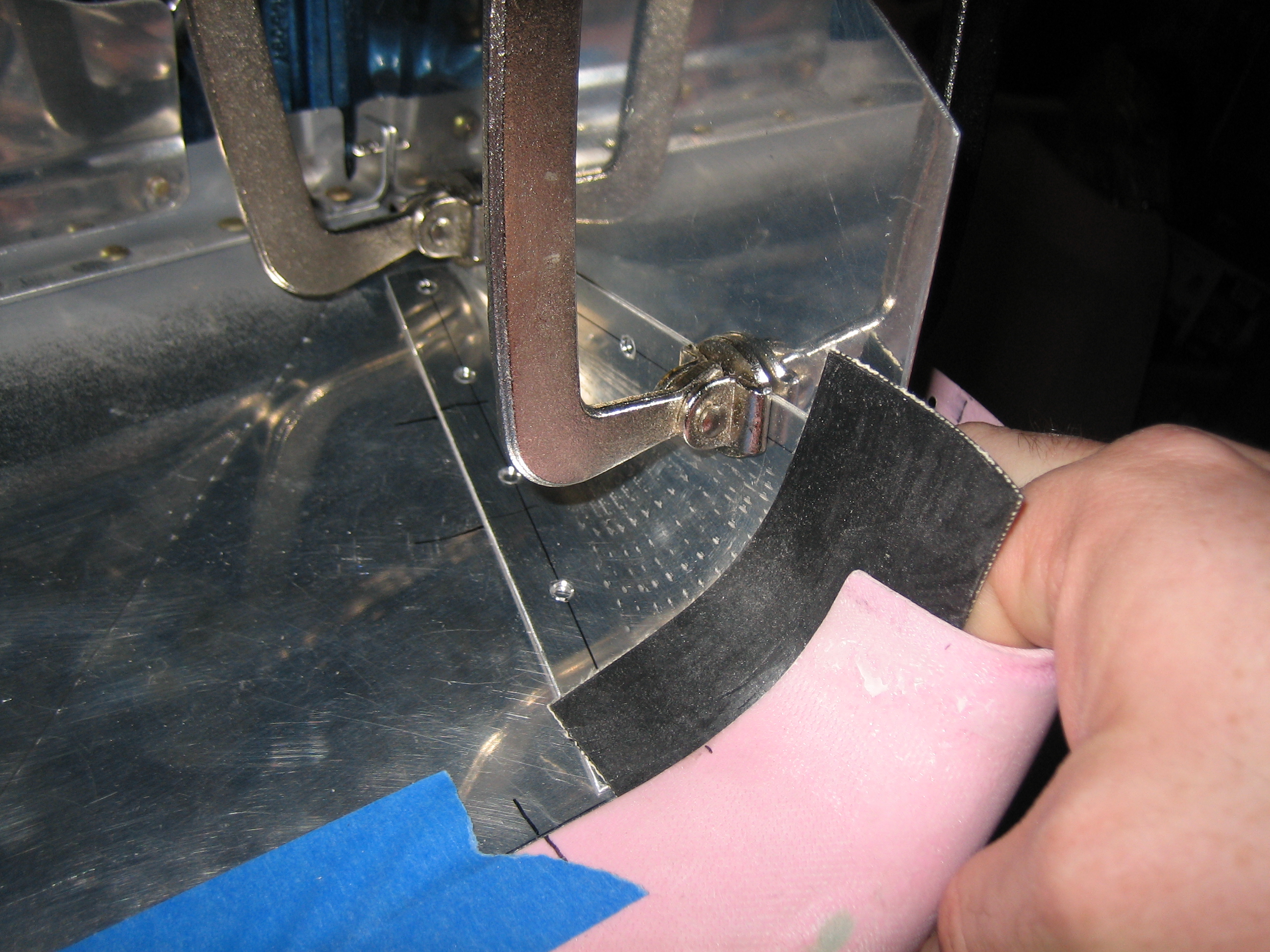
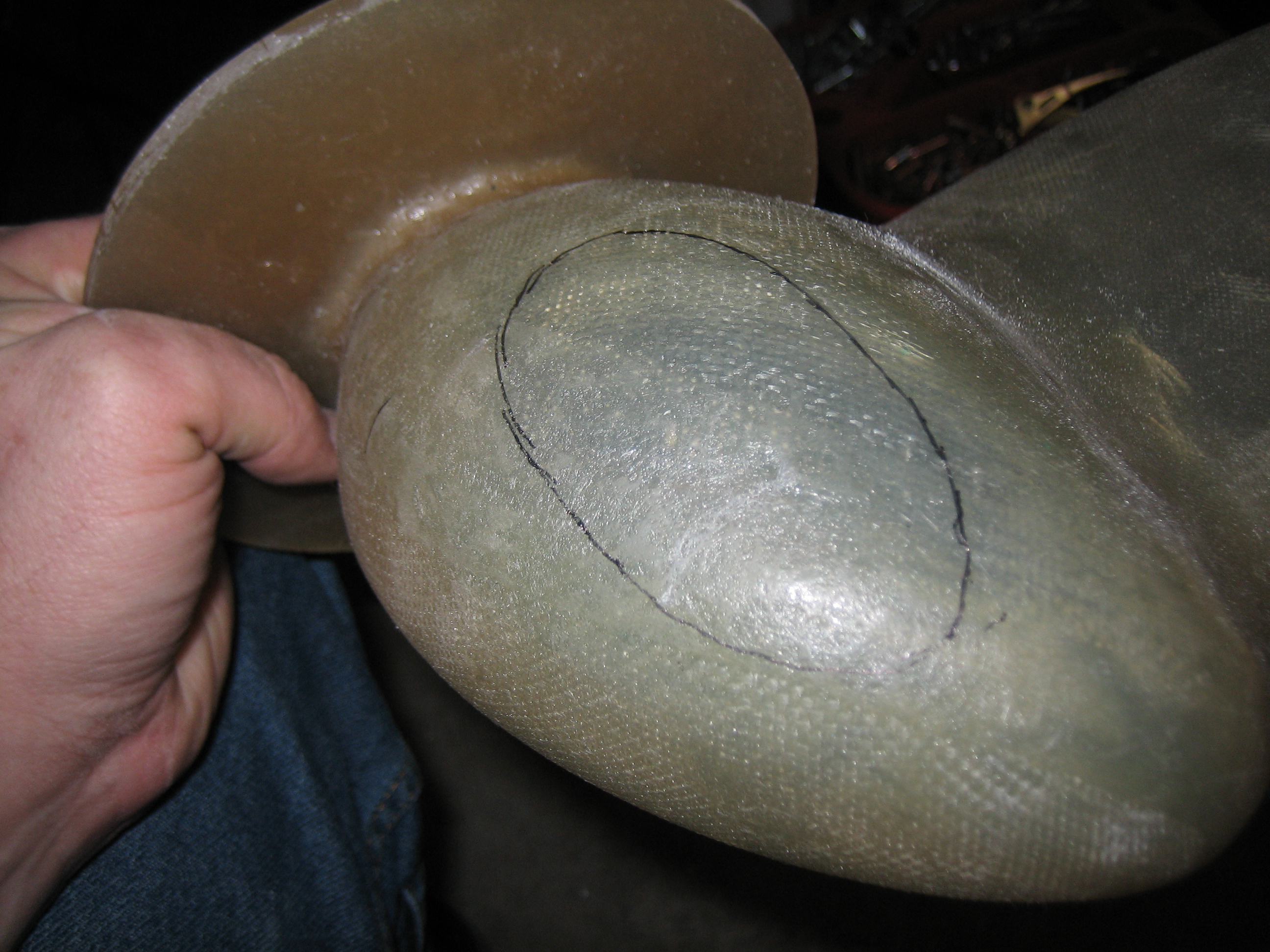
I fabricated the right conical gusset tonight. The way I formed these was to make a template out of stiff paper and transfer it to some 0.032″ 2024-T3 aluminum sheet. I then marked the ends of the curved section and made a serial of small bends by clamping the gusset in a vise and hammering a small wooden block along the exposed face. I then moved the gusset a degree or so and repeated the process until I reached the other end of the curved section.
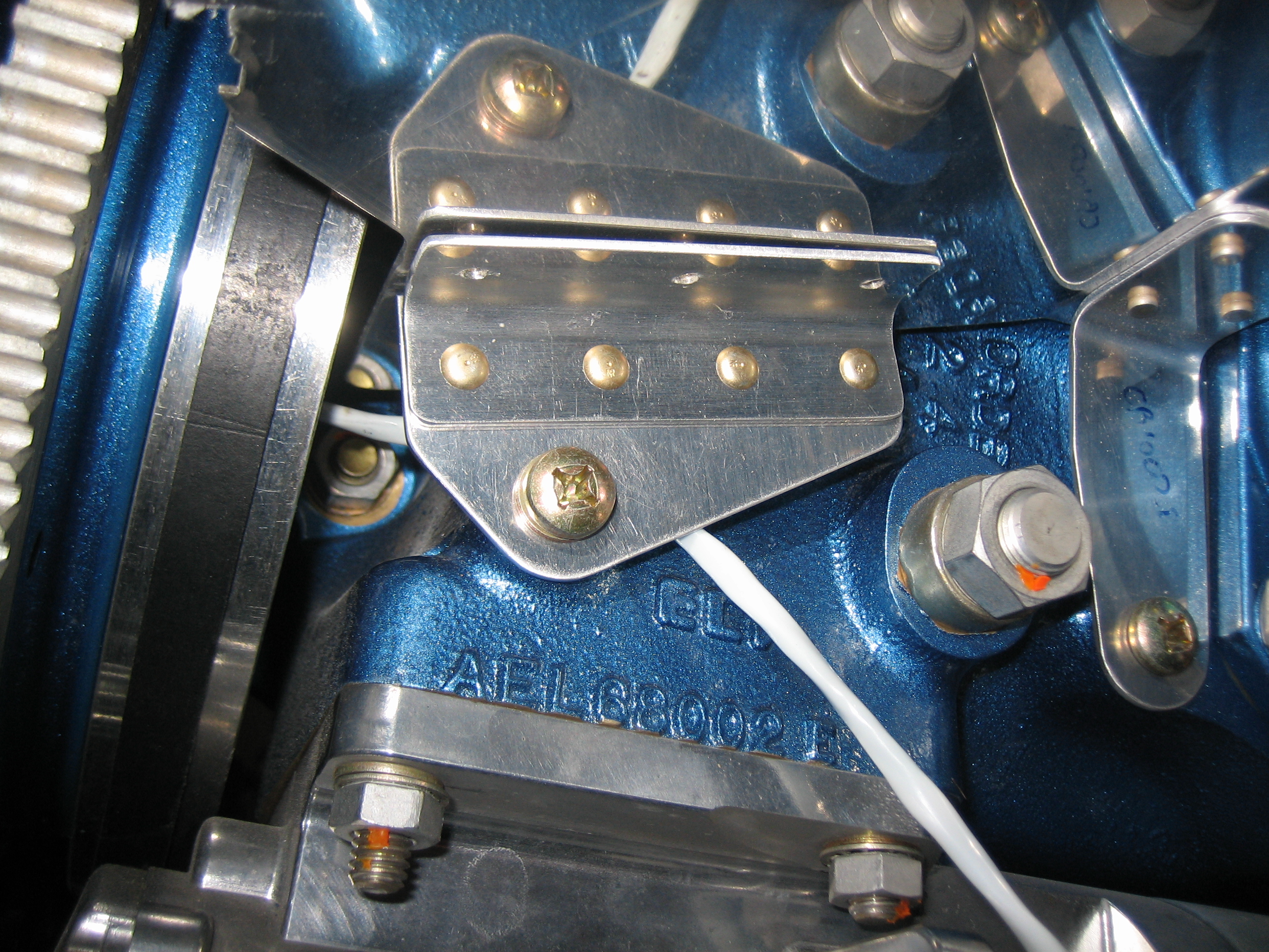
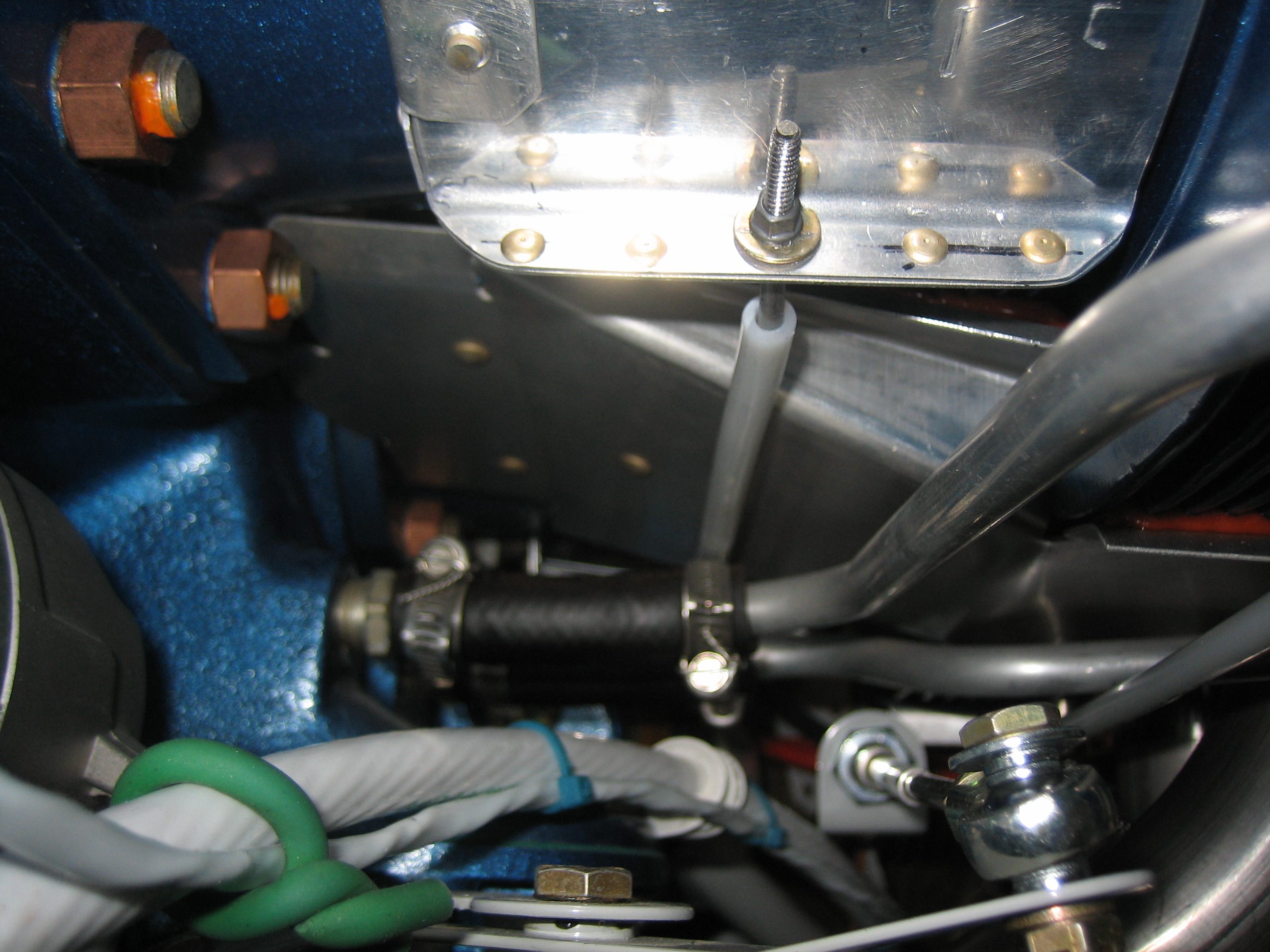
Next, I riveted the mounting angle to the front ramp support.
This is attached to the side of the engine just behind the flywheel.
I then drilled and riveted the support to the front left ramp. Notice that the center hole is left empty. This is because the front baffle wall gusset will be riveted through this same hole.
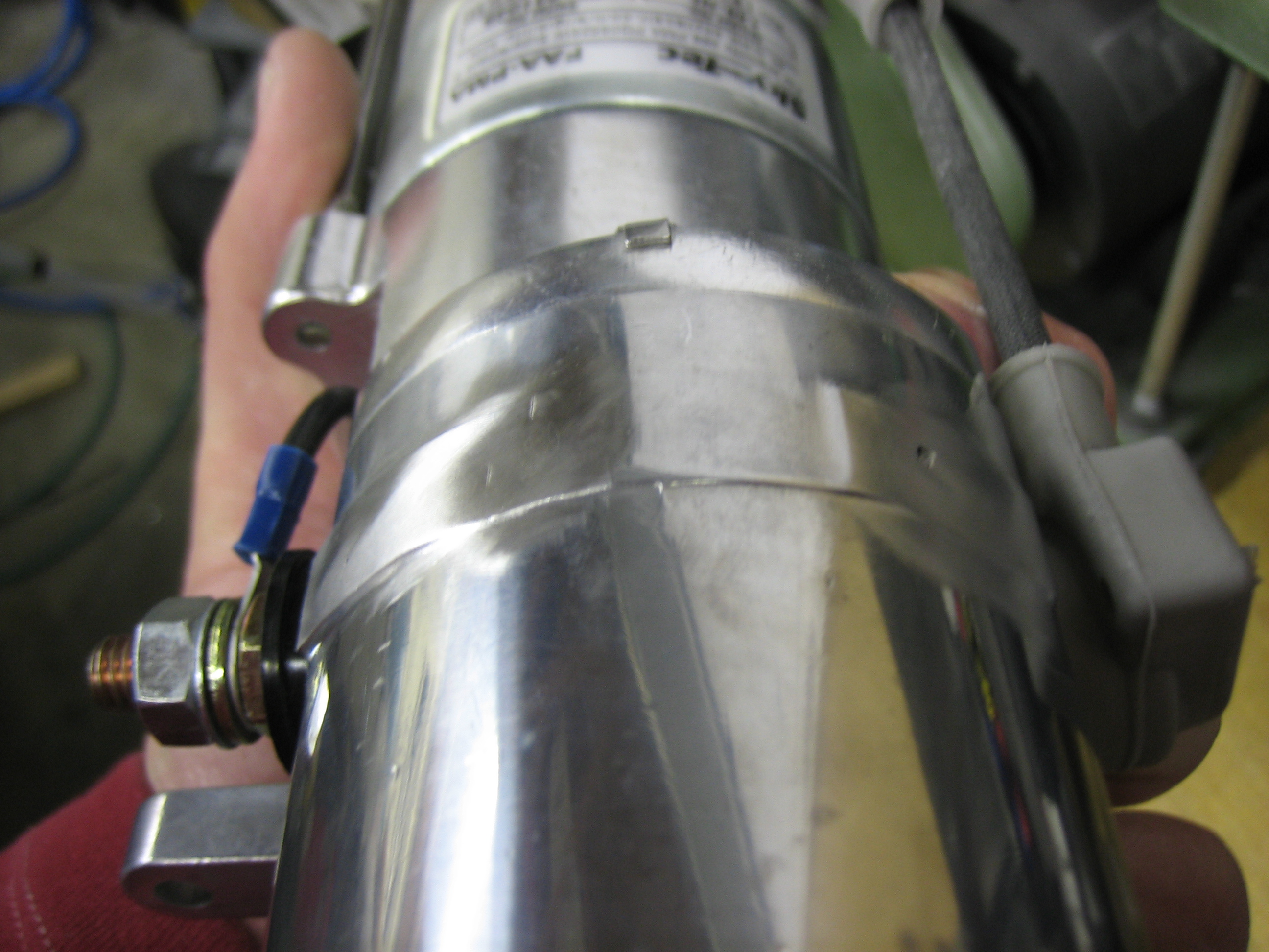
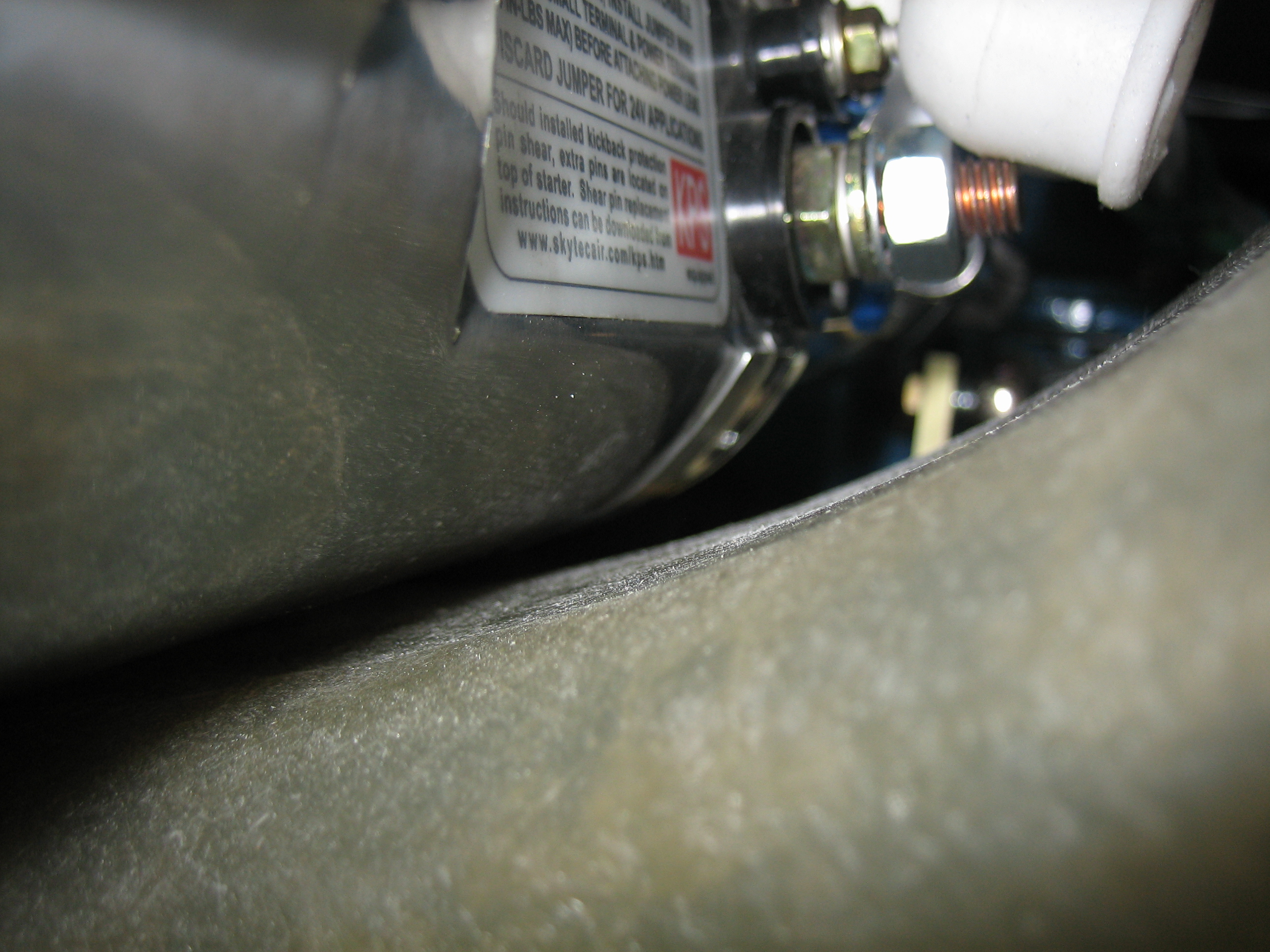
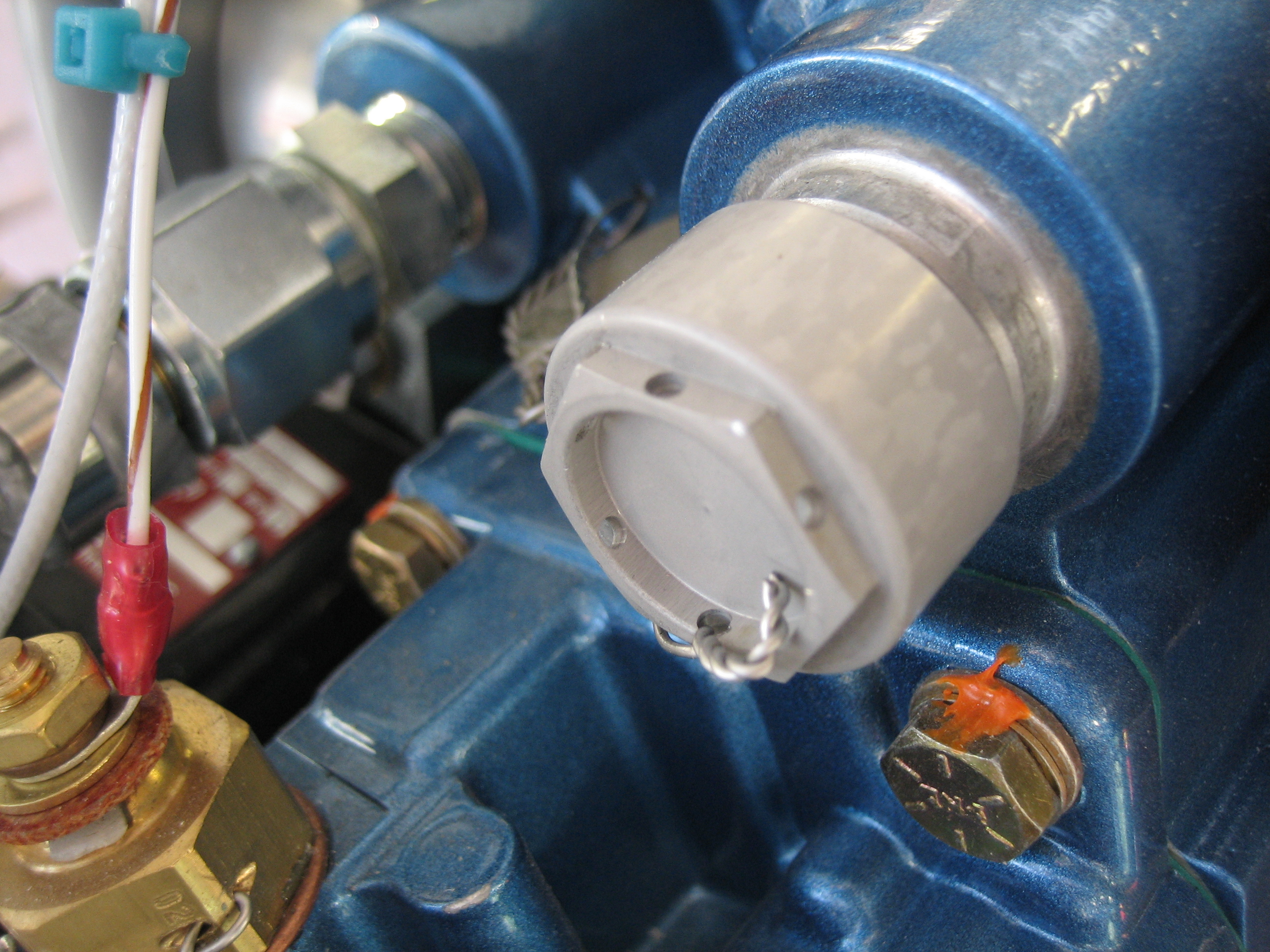
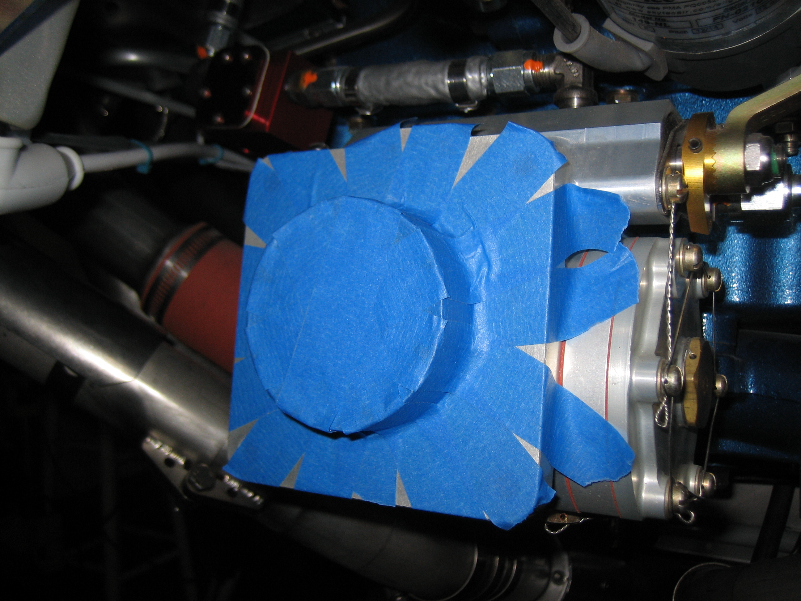
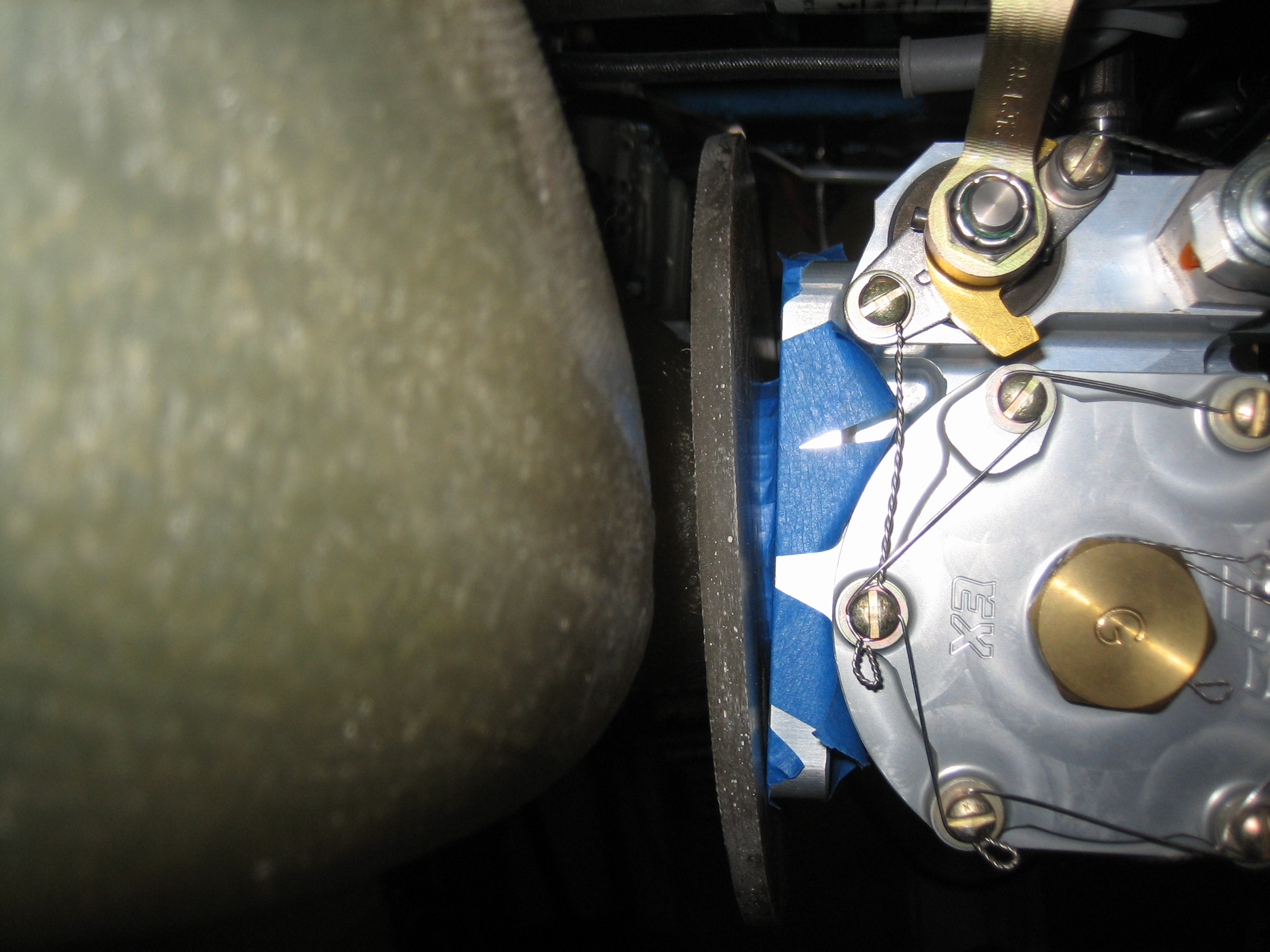
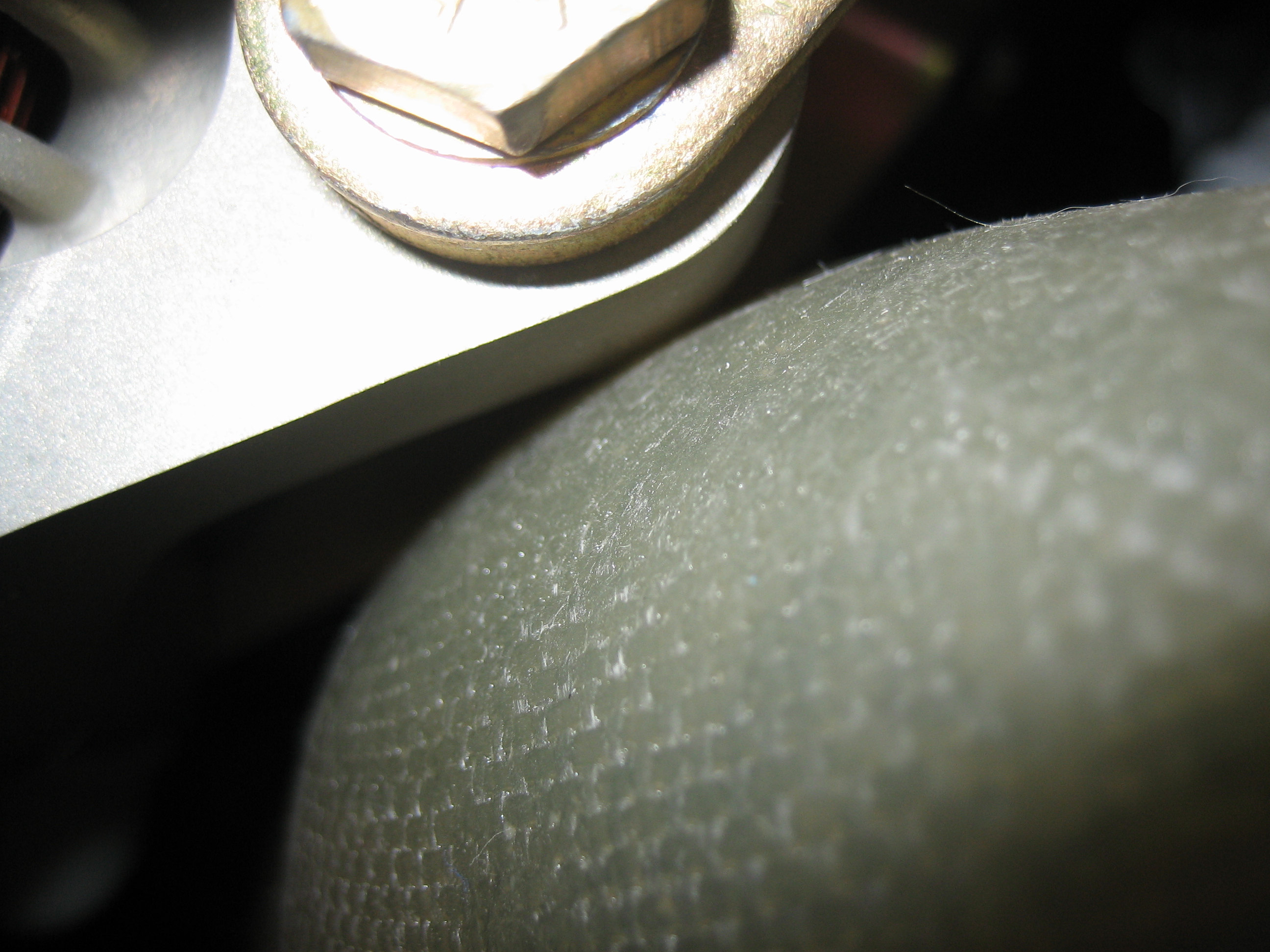
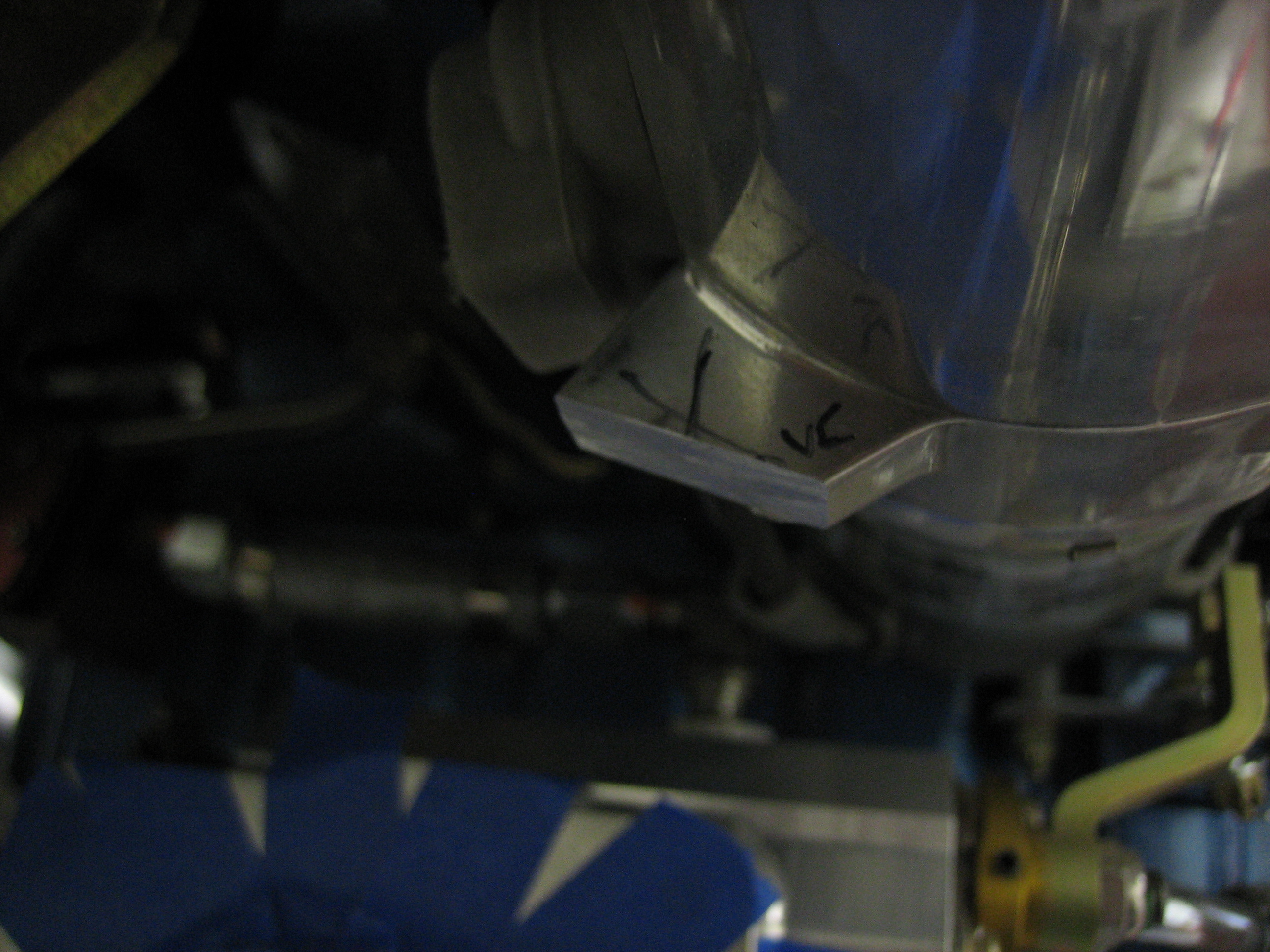
I never liked the old tach cover (see this entry). Although it was safety wired, that didn’t prevent it from unscrewing and bouncing around behind the engine. I recently found out that Andair made this nice machined tach cover with integral o-ring. I swapped it out and safety wired it to the same spot on the engine. There’s no way this is coming off.
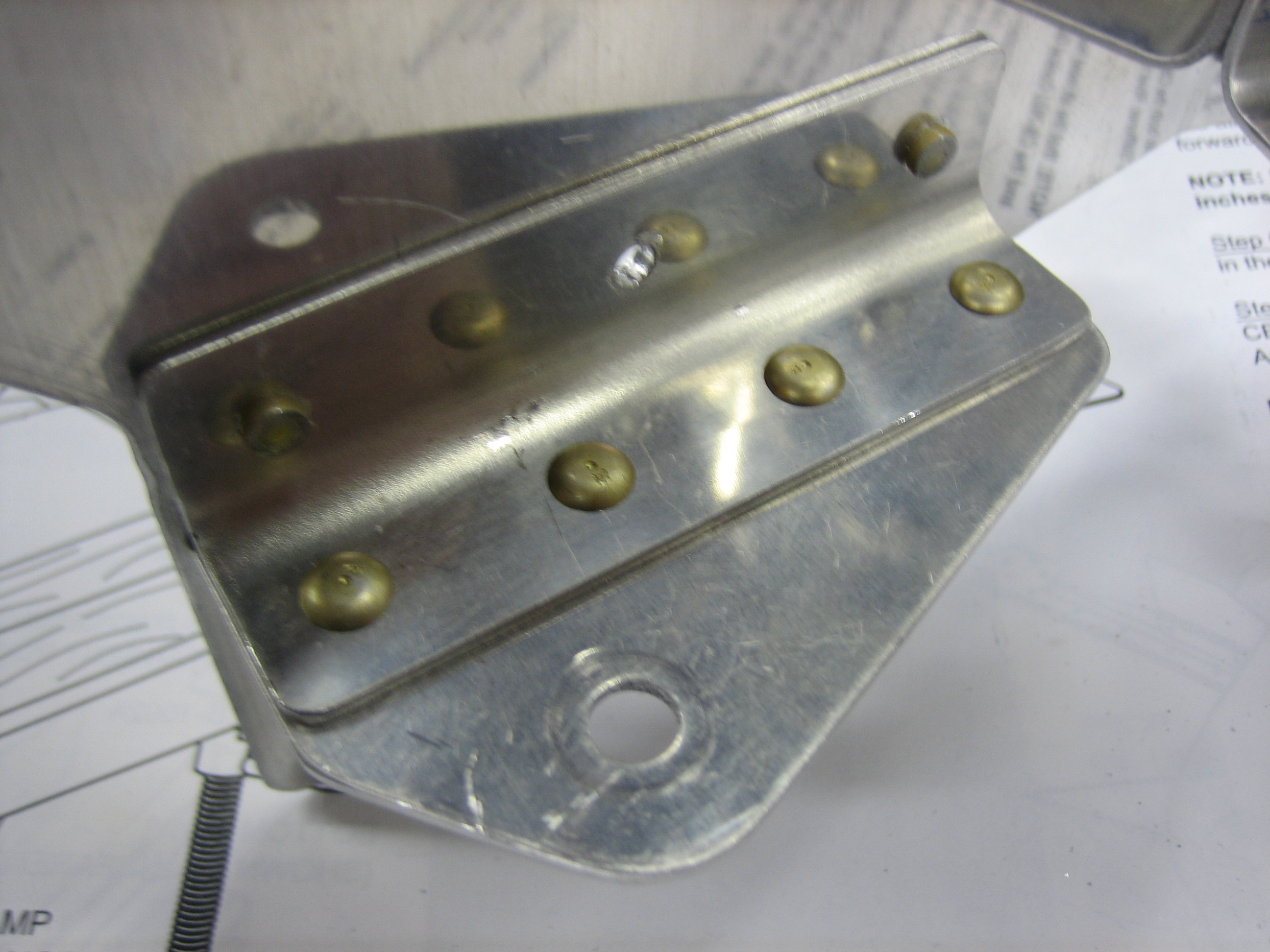
I fabricated the three front ramp support brackets. This is the one that ties the right ramp to the right center baffle. I left the bottom flange long on both ends until I know the left-right position of the vertical face. I’ll then drill this to the right ramp and cut the ends of the flange parallel with the angle on the left.
These are the brackets that tie the left ramp to the left center baffle. I positioned the vertical face against the side of the lower cowl inlet (with a piece of baffle seal between them) and then drilled the support on the left to lock in the position. I then pulled the lower cowl and back drilled the support on the right through the existing hole in the ramp and support that sits just under the ramp. I then pulled the bracket and drilled two more holes in line with that hole and then match drilled them to the ramp. Getting all of this in the right position was a little tricky until I figured out the order, but everything worked out nicely.
I deburred everything and riveted the support brackets to the ramps and front center baffles. The plans call for universal rivets here, but I might have to swap the rivets on the left bracket out for a flush head since the baffle seal material will rest here.
Here’s the bracket for the right ramp.
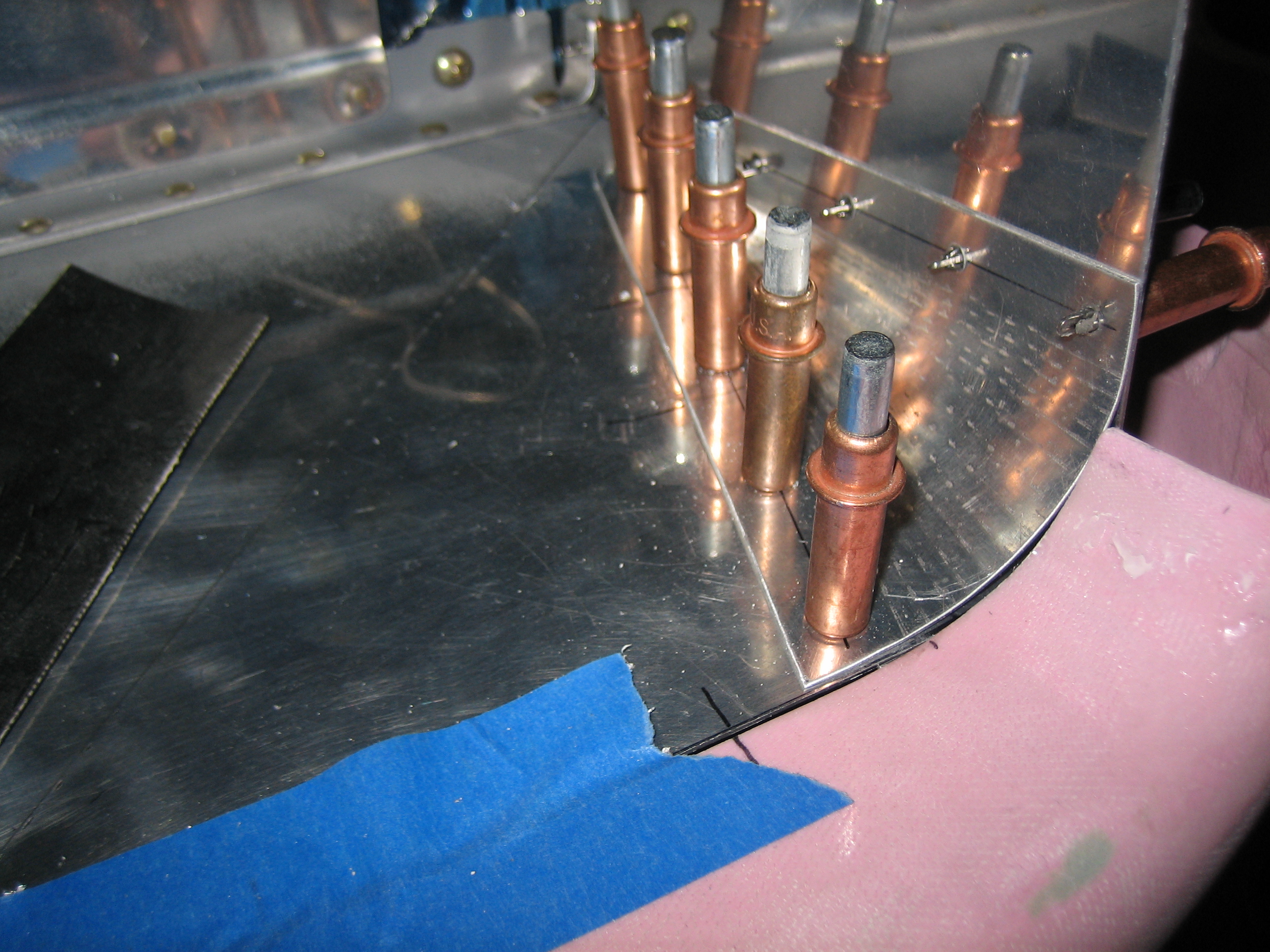
I used some baffle seal material to position the conical gussets and side baffles, then drilled the gussets to the ramps and side baffles.
With the conical gussets in place, the front baffles are significantly stiffer.
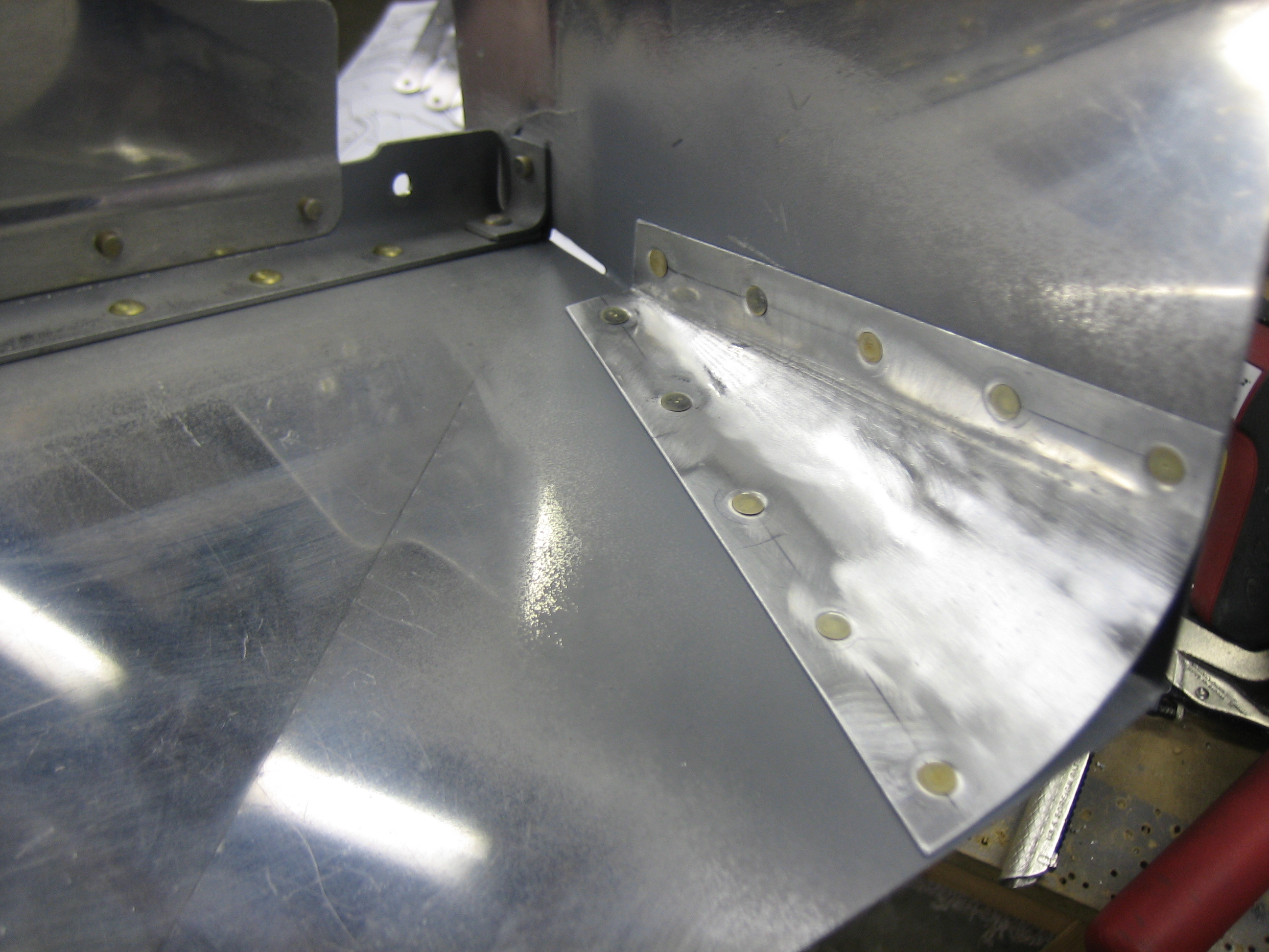
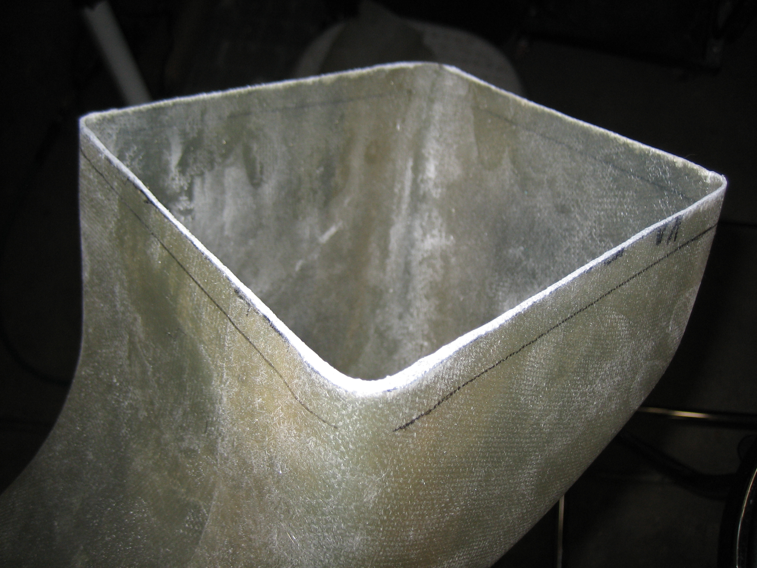
I finished drilling the side baffle flanges to the ramps and then deburred and dimpled everything. After a quick priming of the mating surfaces, I riveted the conical gussets in place. Here’s the right gusset. I also riveted the little clip in the upper right of the picture to the side baffle.
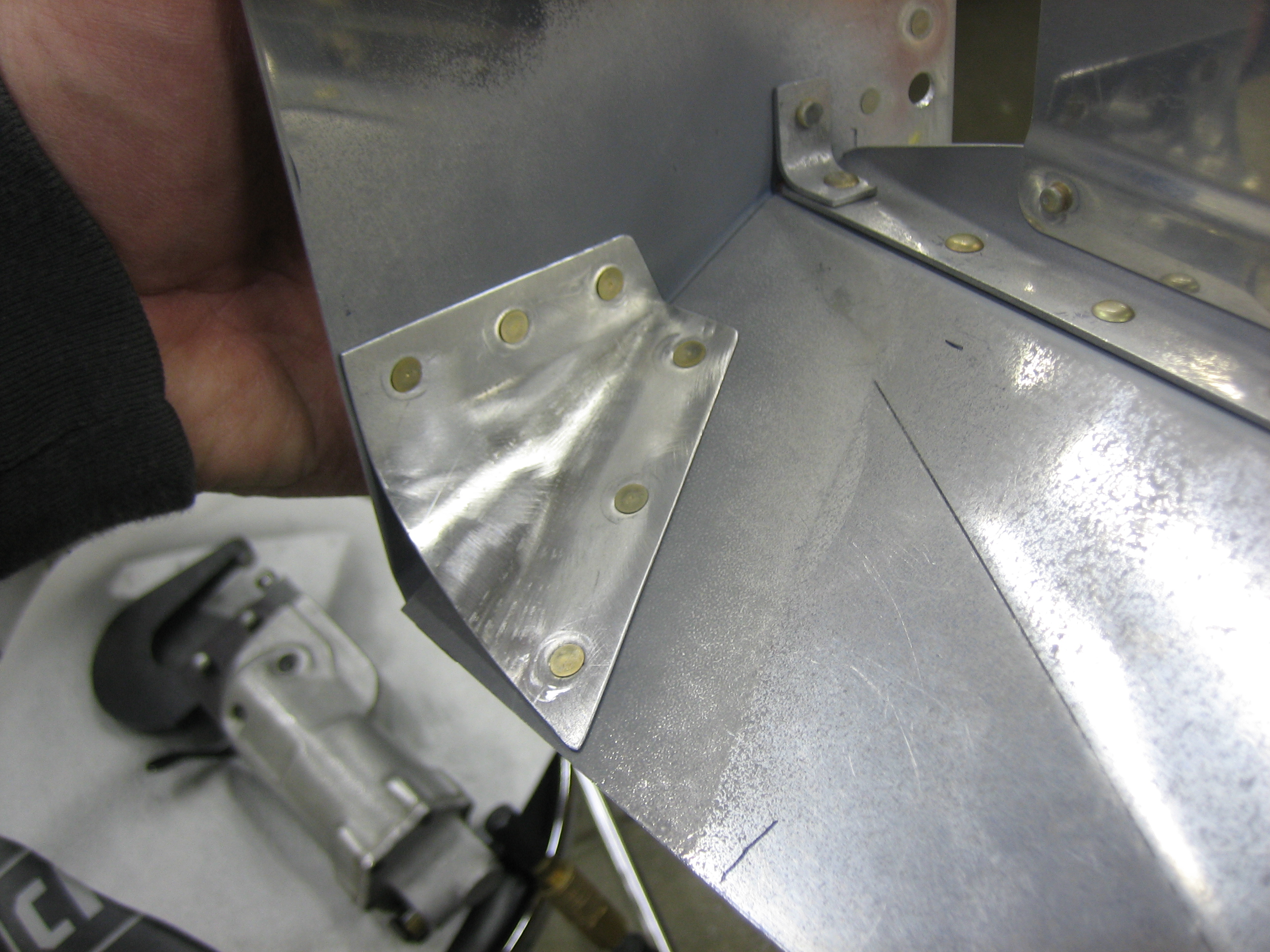
Here’s the right conical gusset. These ended up fitting really nicely. There quite a bit harder to install now since they’re so big. They wrap from the centerline of the engine just behind the prop around the side of the engine and back past the front-most cylinders.
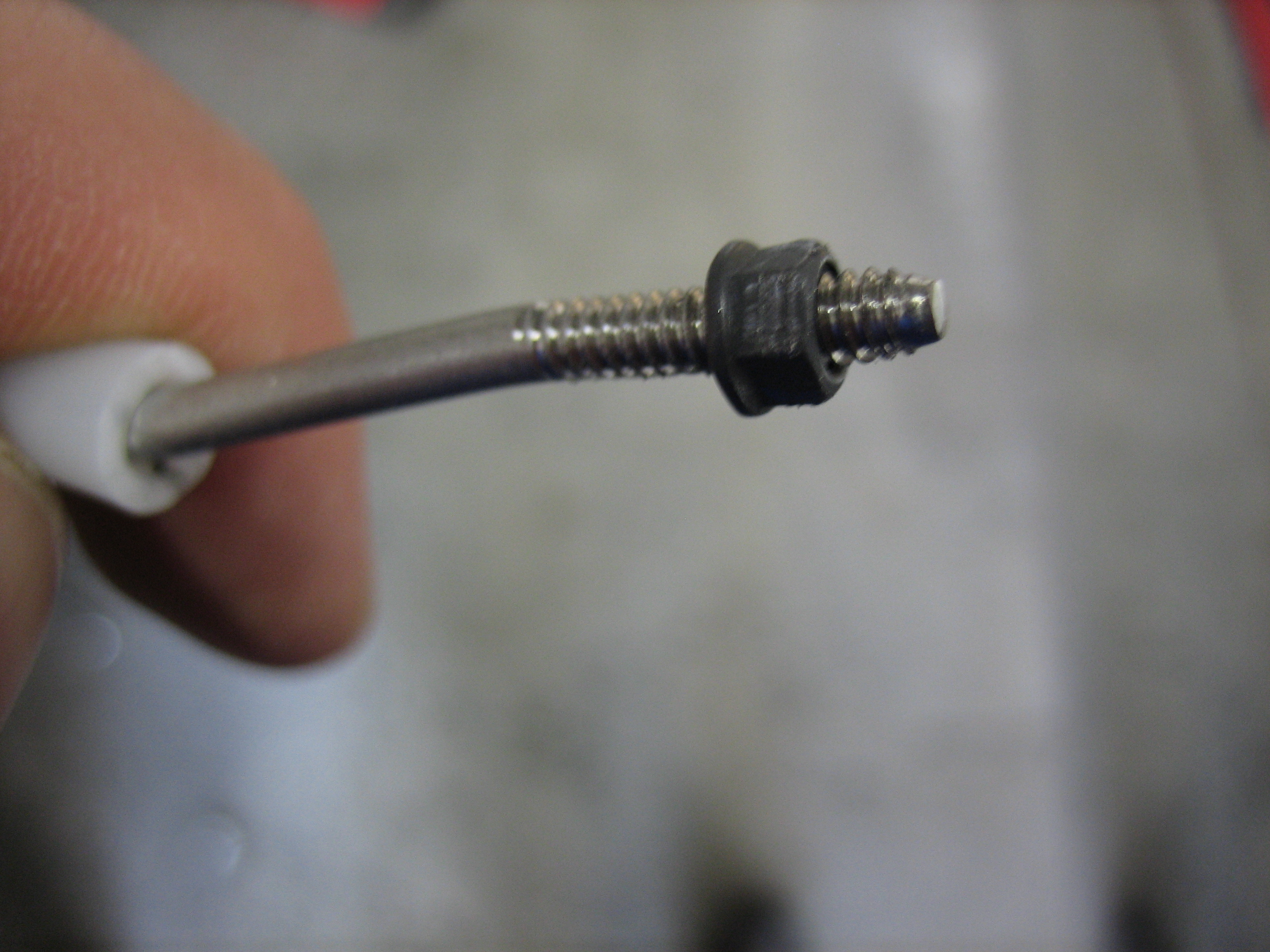
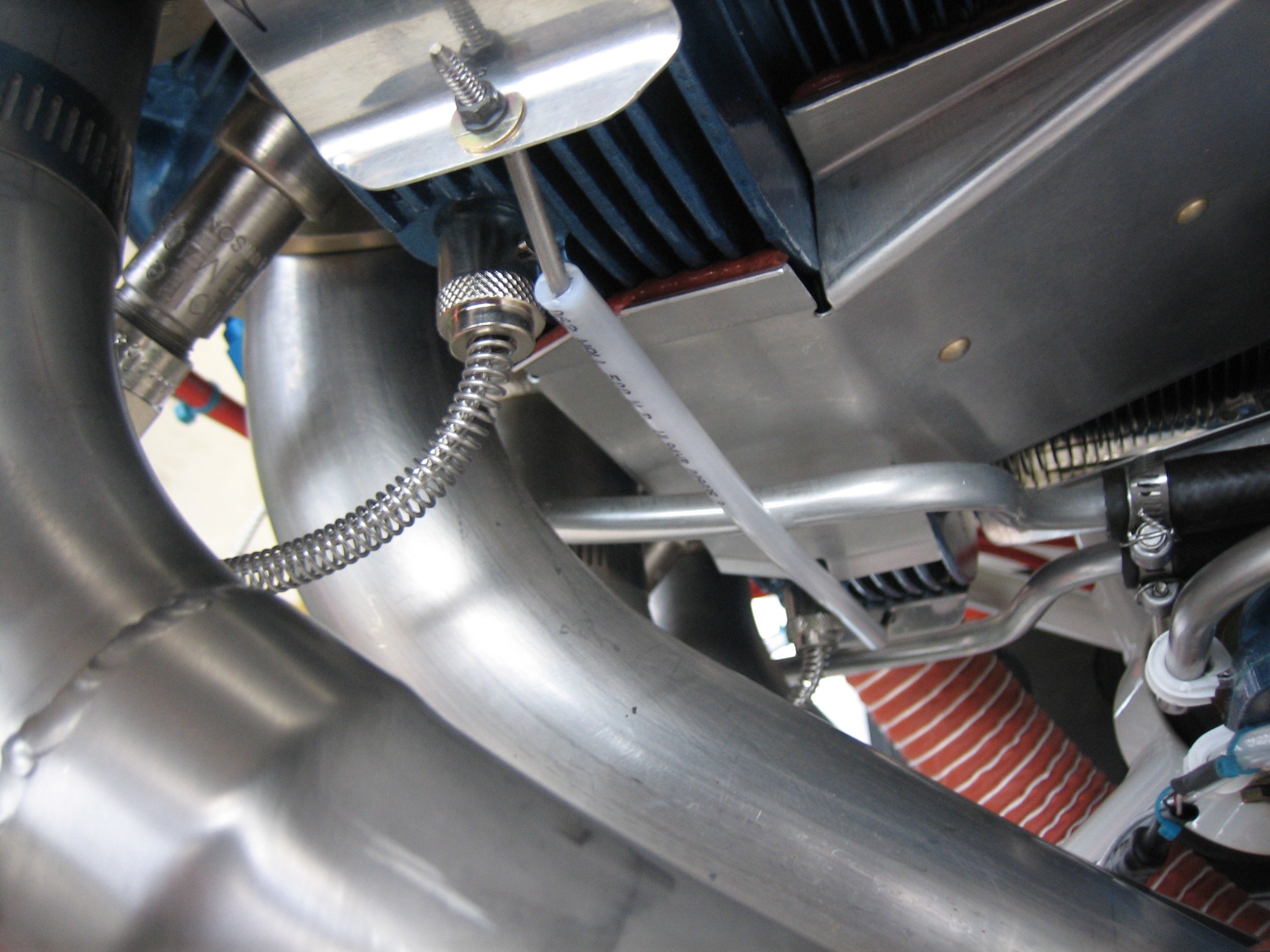
The bottom of the baffles need to be tied together to keep them tight against the cylinder fins. You can either do this by using safety wire through some washers (to keep the safety wire from sawing through the aluminum baffles) and a piece of plastic tubing (to keep the safety wire from sawing through the cylinder head oil return lines. I’m sure this works fine, but it seems pretty cheesy. The other suggested approach is to use some stainless steel rod, bent to clear the cylinder head oil return lines and threaded for 6-32 nuts on each end. I got started by fabricating the left outboard connecting rod. This needed to be a little longer than the plans specified, and the angle of the bends at each end differs from the plans to make the threaded ends sit perpendicular to the baffle flanges. I installed the optional plastic tubing to ensure that there would be no abrasion if this contacted the oil return line. I tried threading the end, but the shitty Harbor Freight tap and die set I have is really junk. I basically stripped the threads on the 6-32 die. This junk is okay for creating threads on aluminum, but I need a decent tap and die set to do stainless steel.
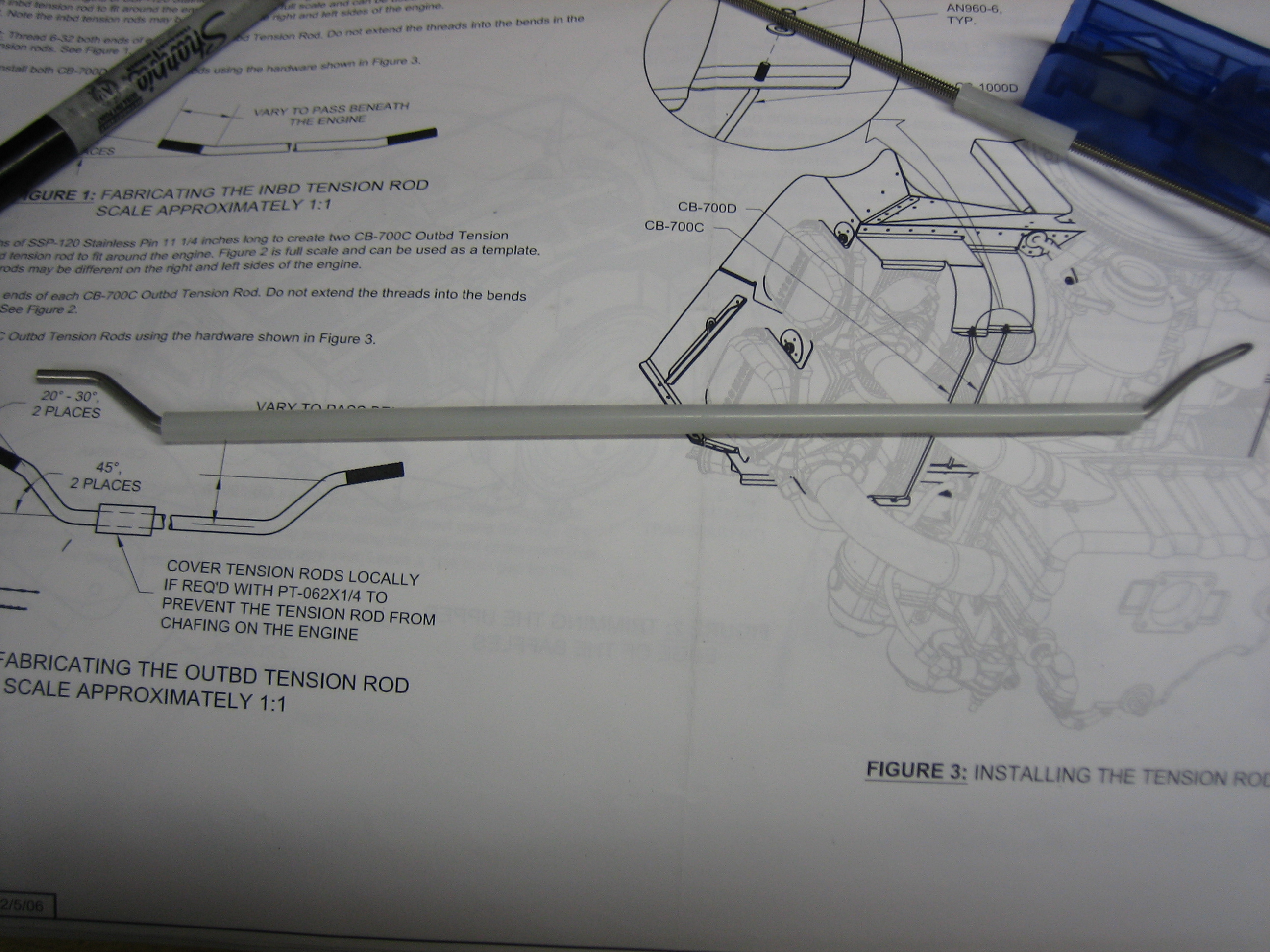
I picked up a much better tap and die set from Sears today and was able to easily thread the ends of the stainless steel rod I bent yesterday. Unfortunately, the die cuts the threads a little deeper than a typical 6-32 screw, so the all-metal self-locking MS21042 nut spins freely. I’ll have to further distort the threads in a vice to ensure these are self-locking.
I finished fabricating the outer baffle connecting rods. Here’s the one on the left side of the engine.
I put a fairly healthy curve in the rods. This way they stay fairly straight even under tension.
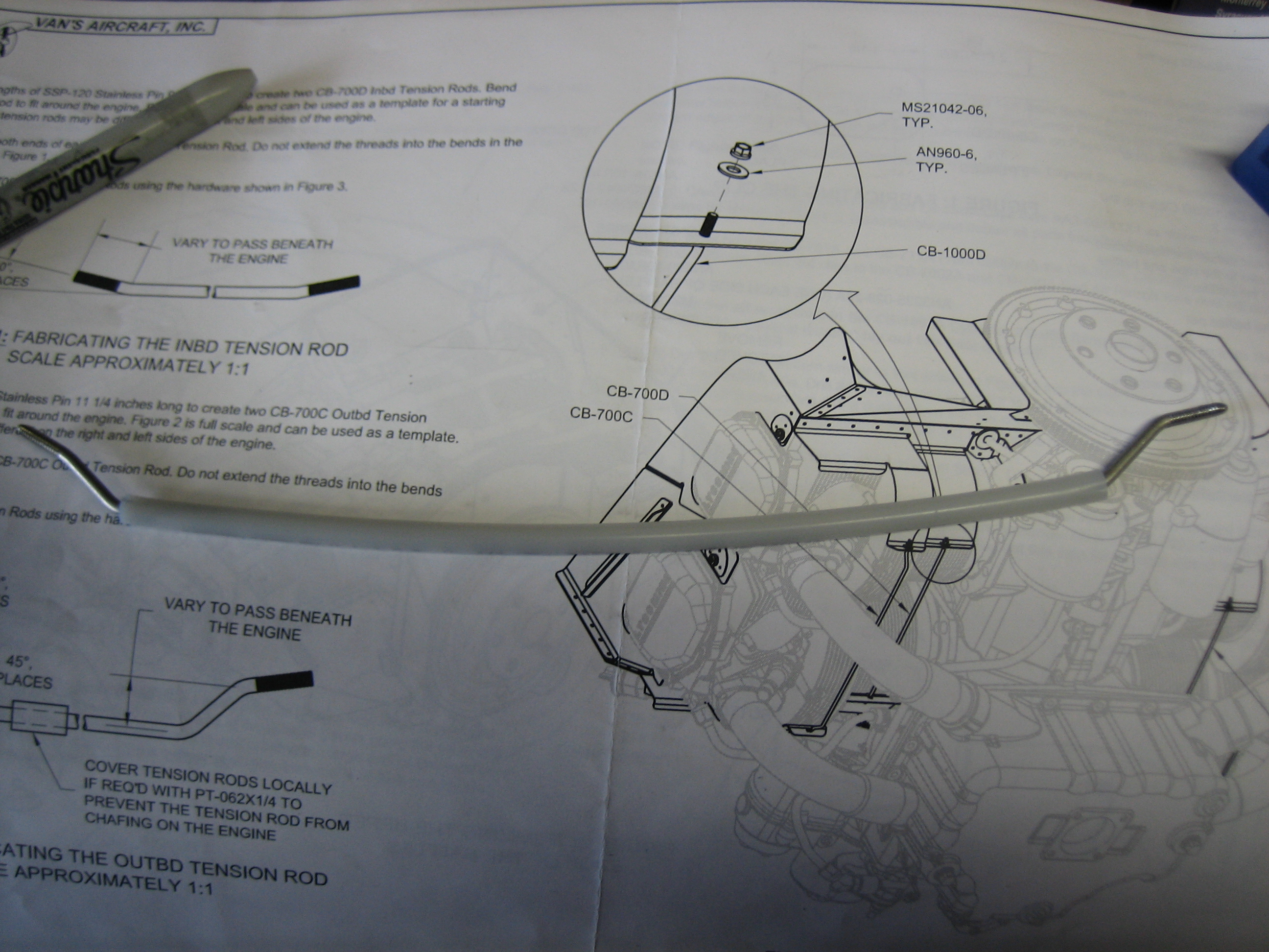
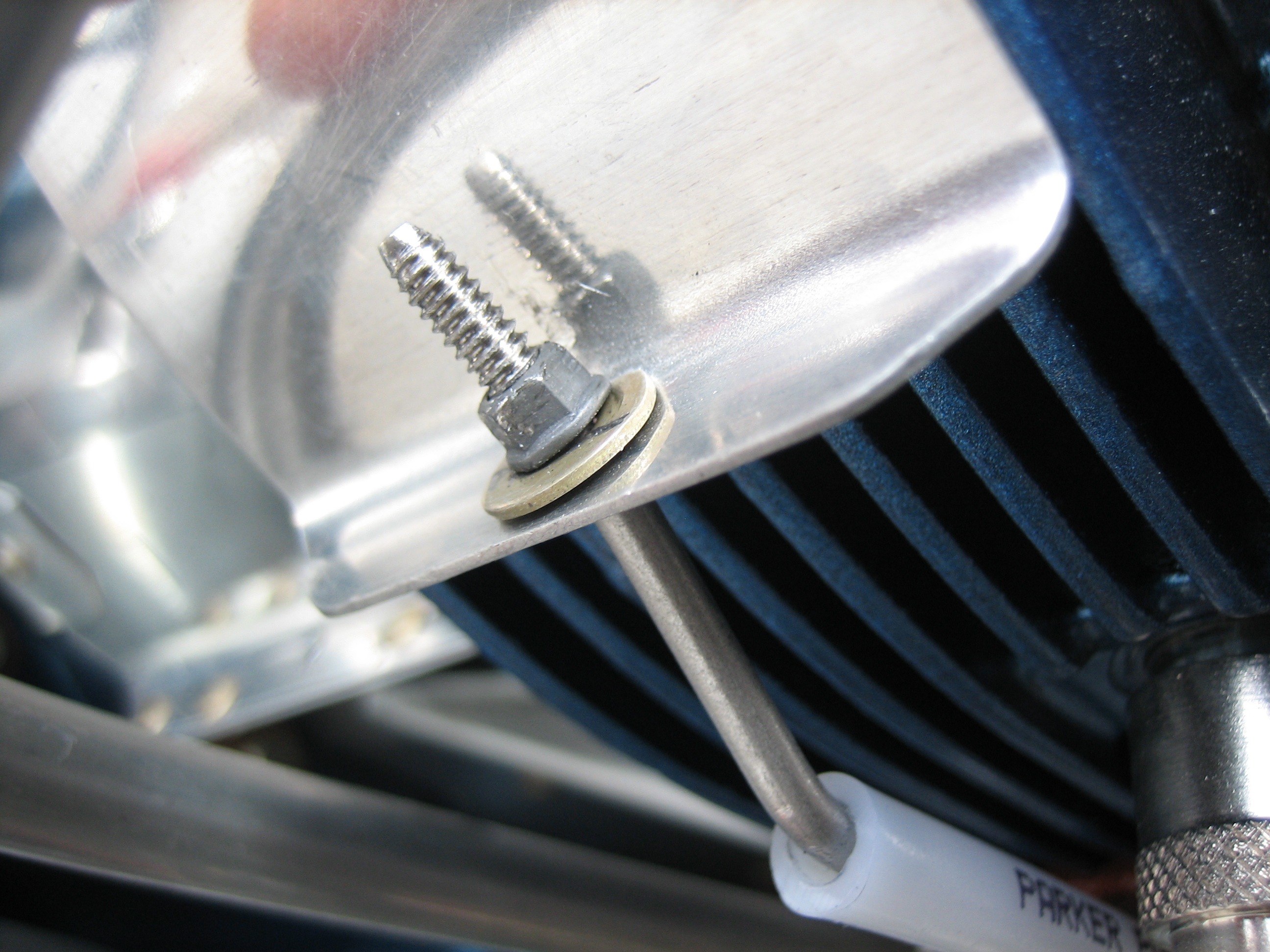
Here’s the one on the right side of the engine. Both outer rods touch the cylinder head oil return lines, but the curve I put in the rods causes it to just touch the oil line, not put pressure on it. That plus the plastic cover on the rods should eliminate any abrasion on the oil lines.
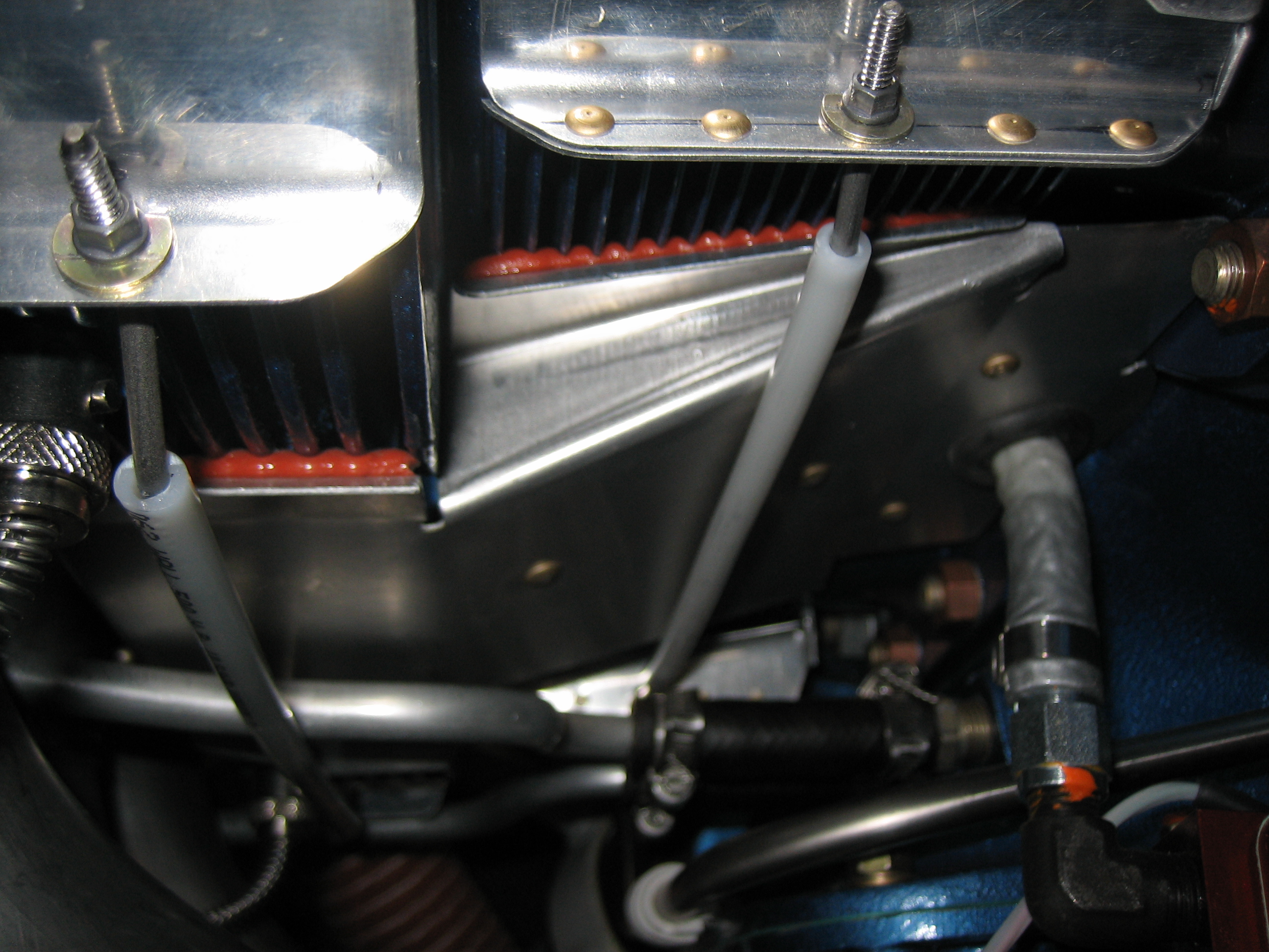
I finished up the inner baffle connecting rods. Here’s the one on the left side of the ending. Getting to the nut on the aft end of this rod is probably the toughest part of installing these.
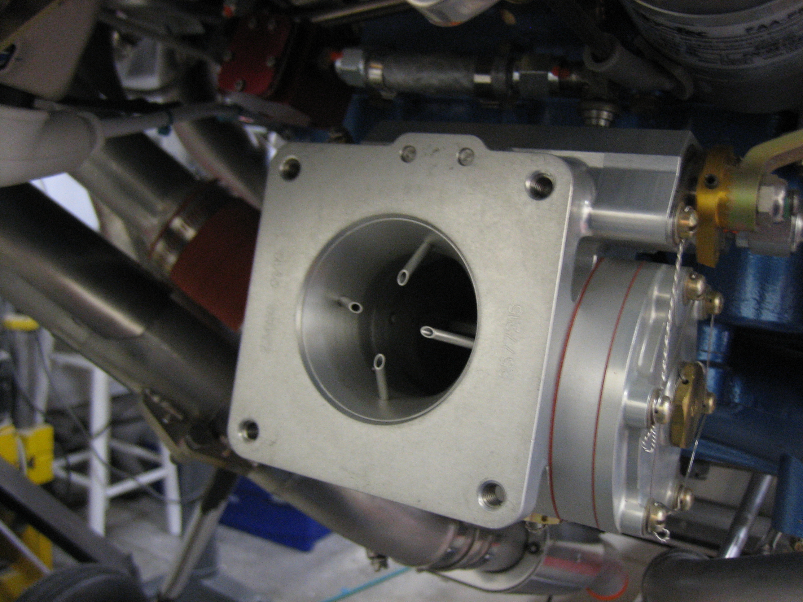
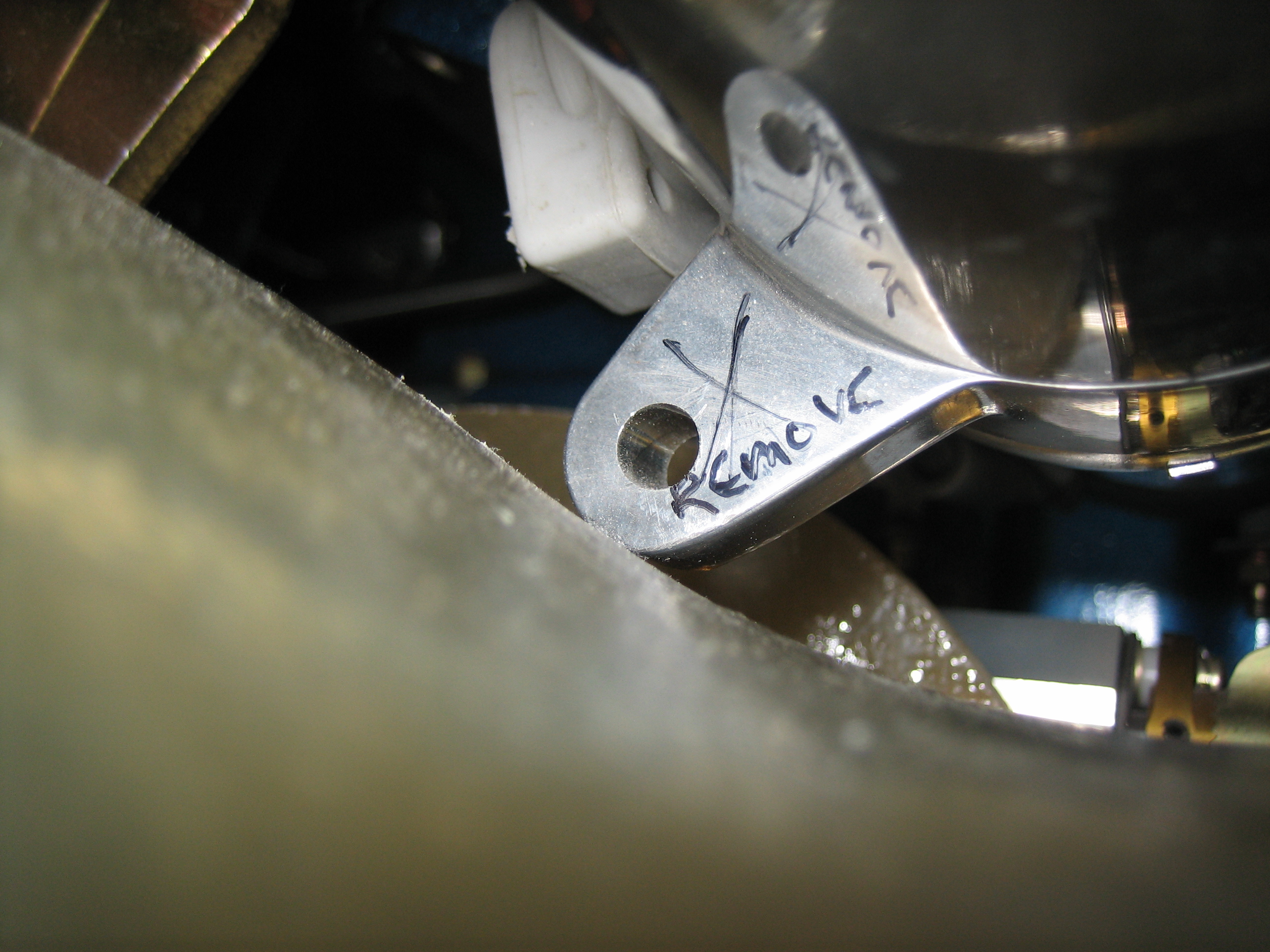
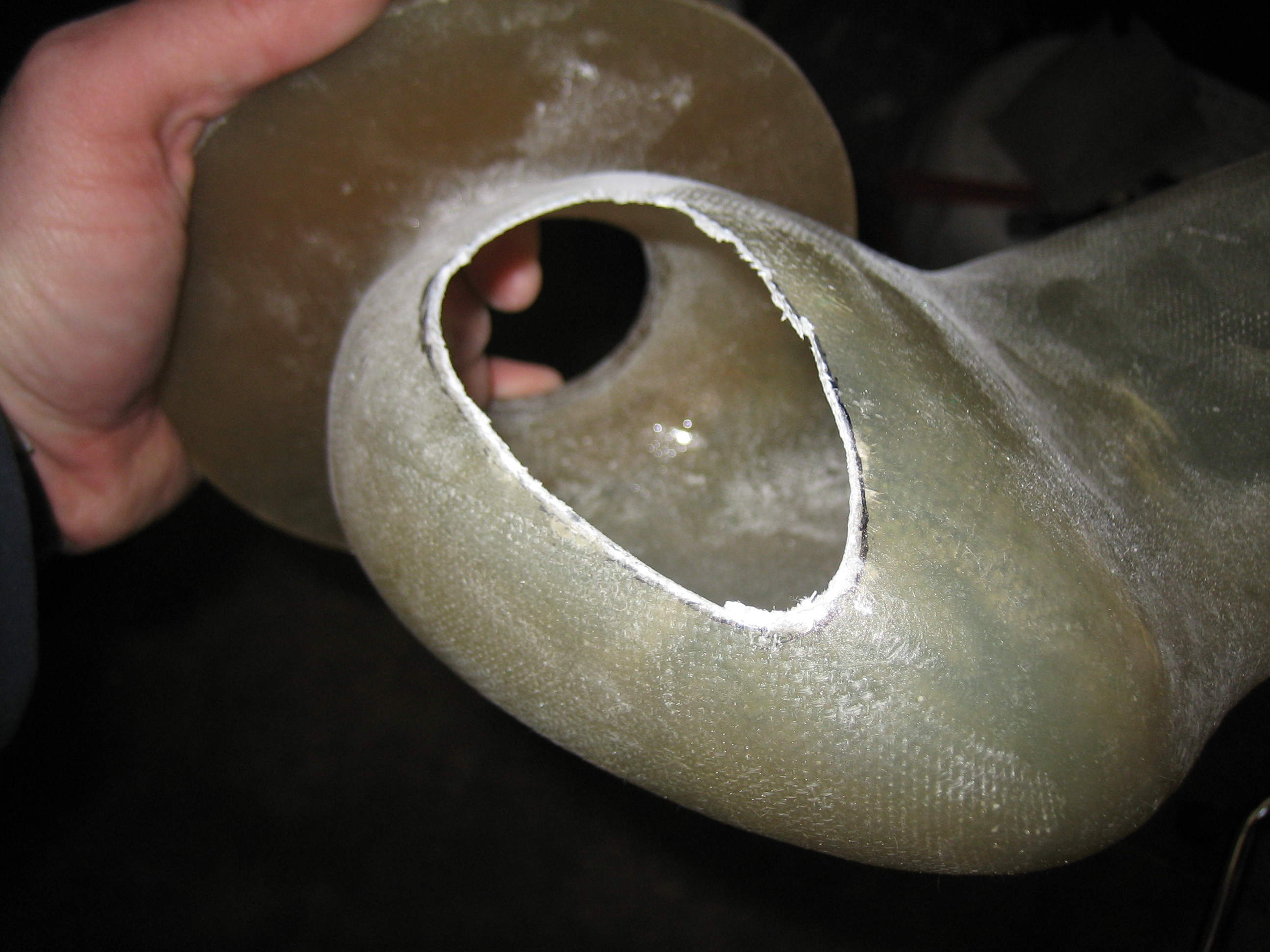
I pulled the starter off the engine and filed off the two lower lugs to provide clearance for the snorkel.