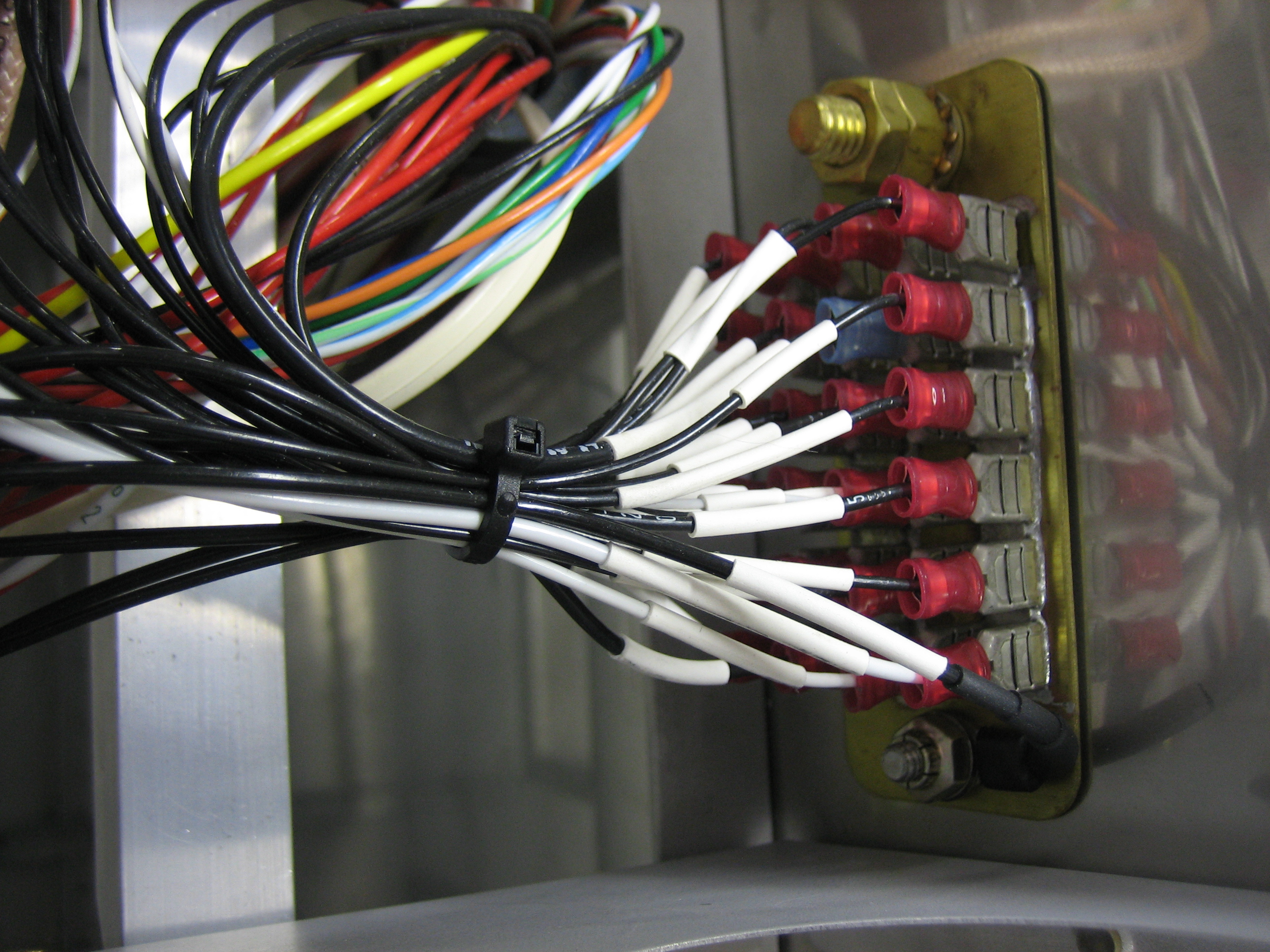
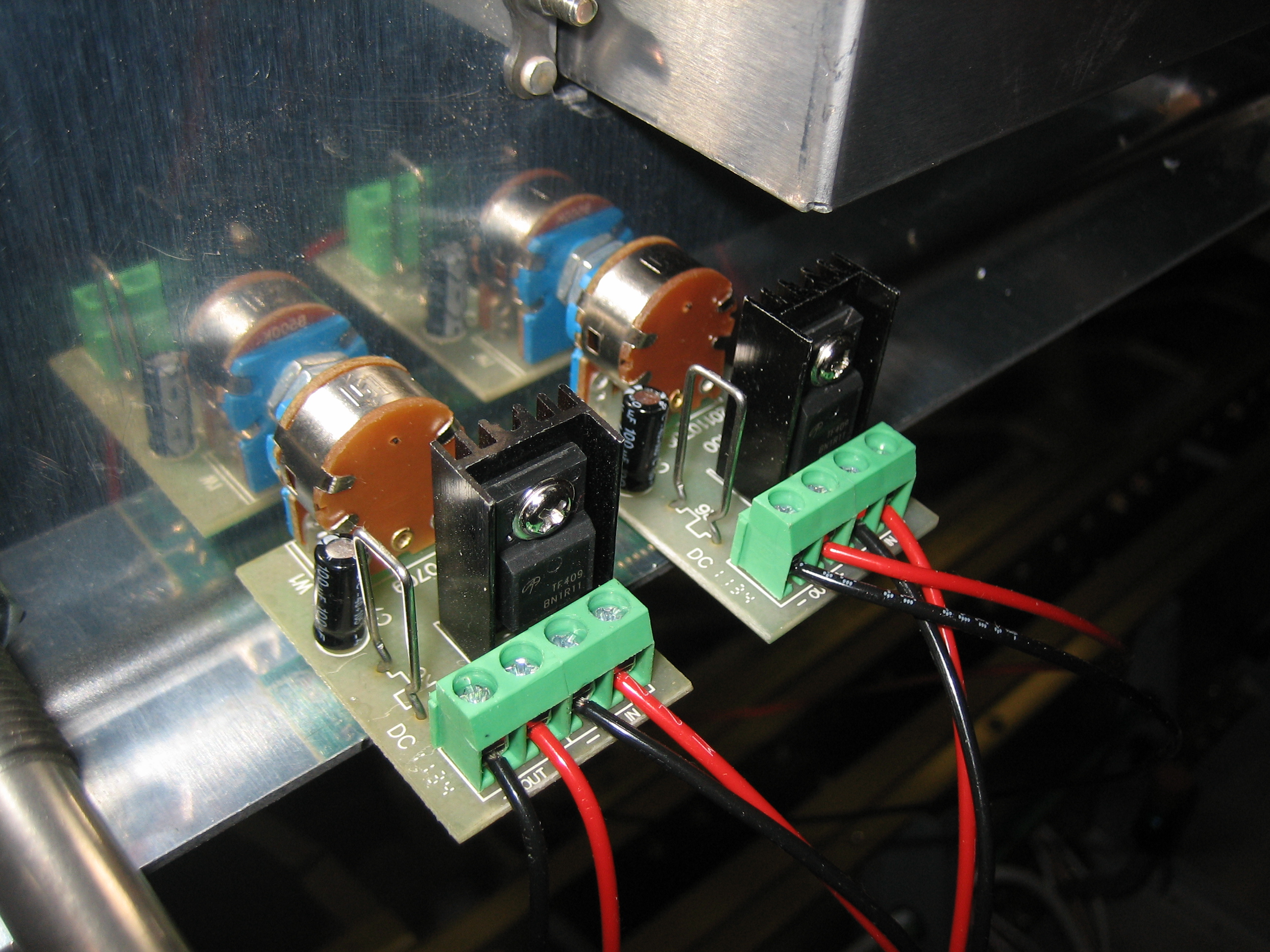
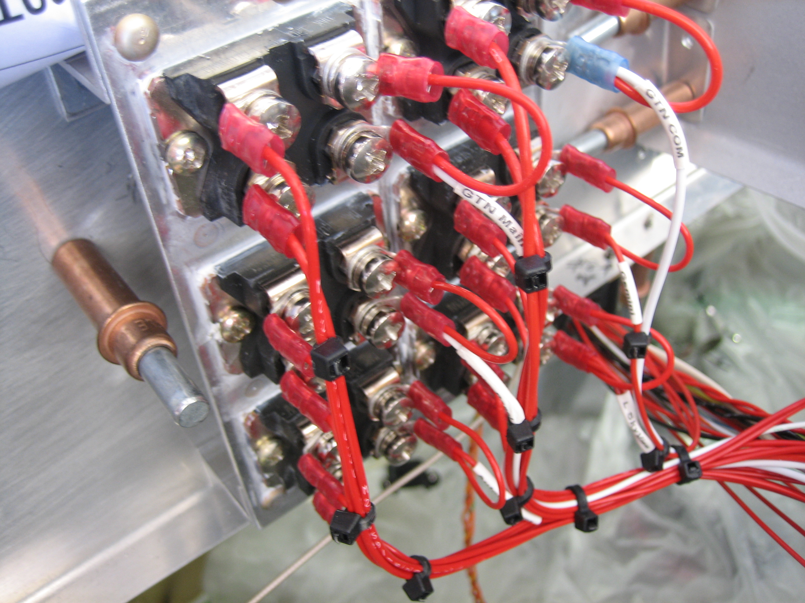
I finished up all of the isolation diode wiring and tidied up the wires. I then torqued all of the screws down with a torque screwdriver.
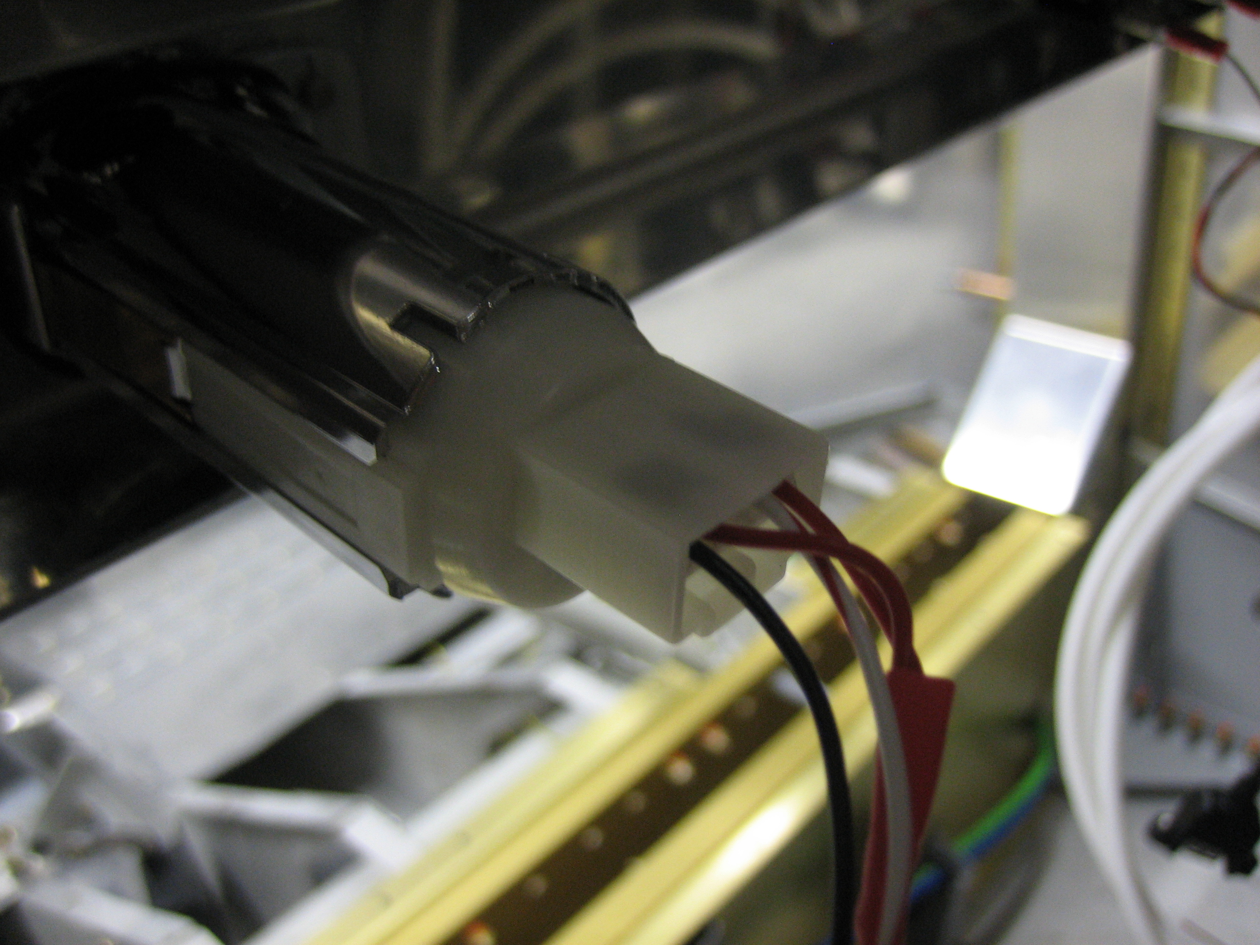
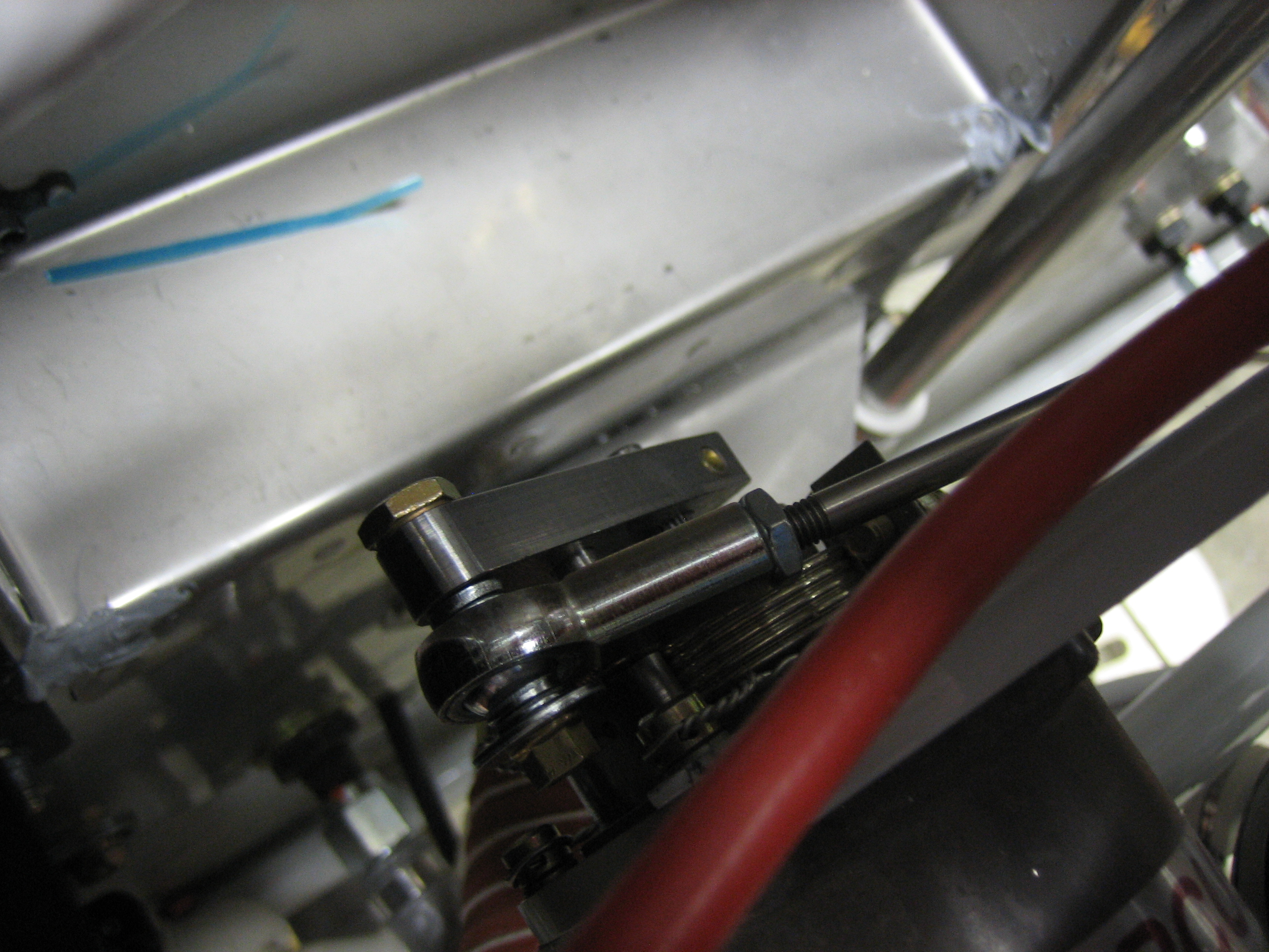
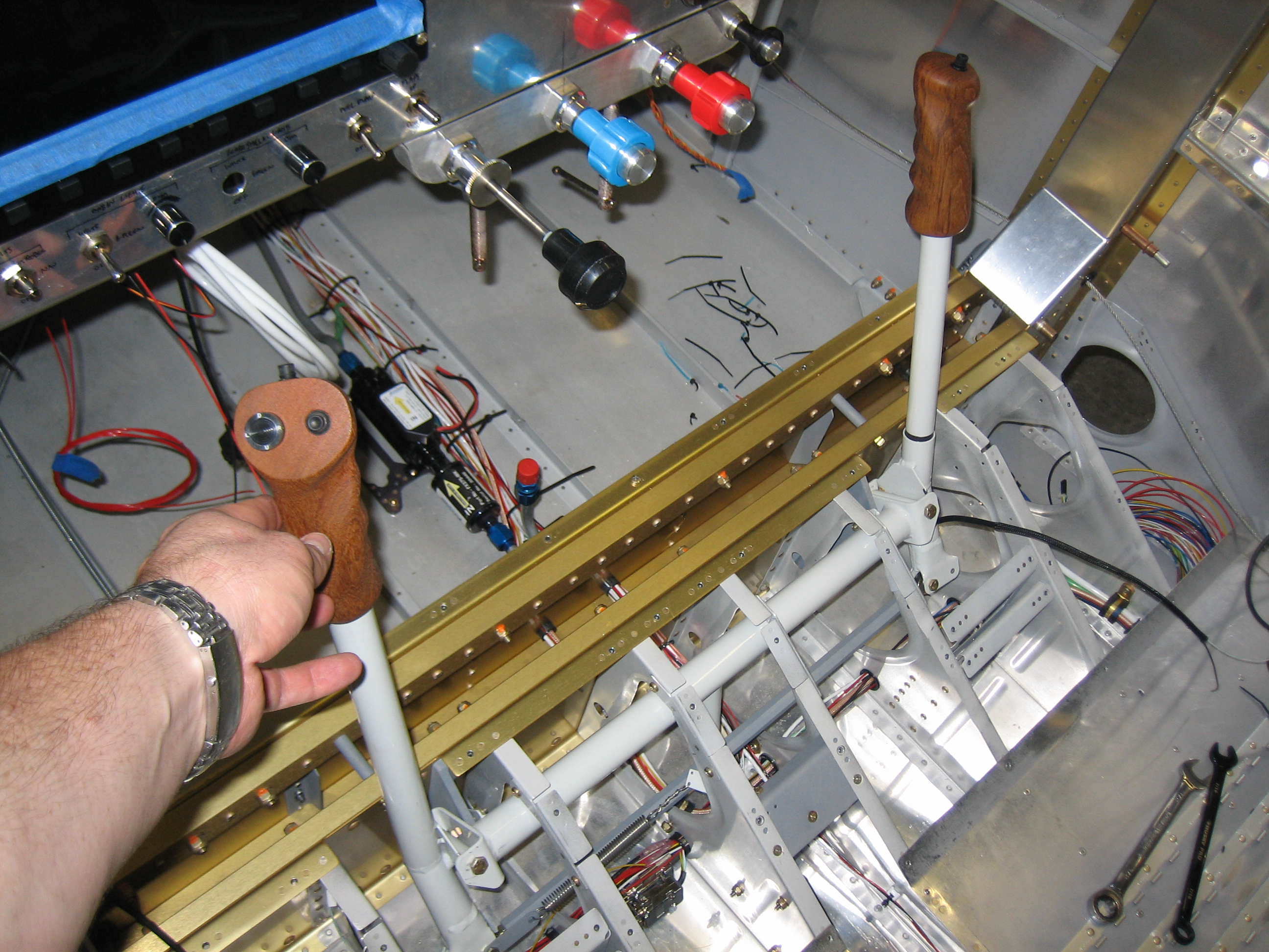
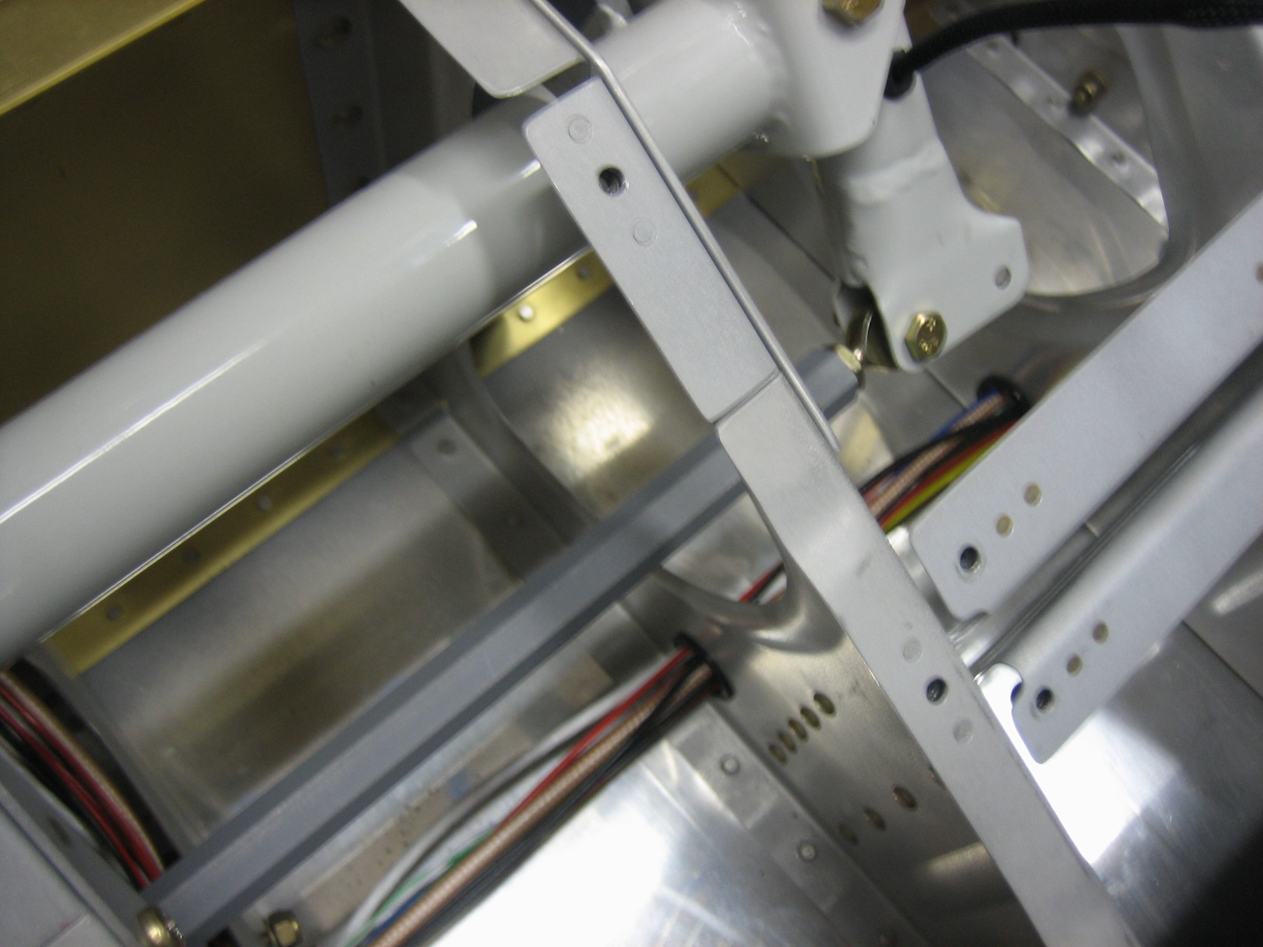
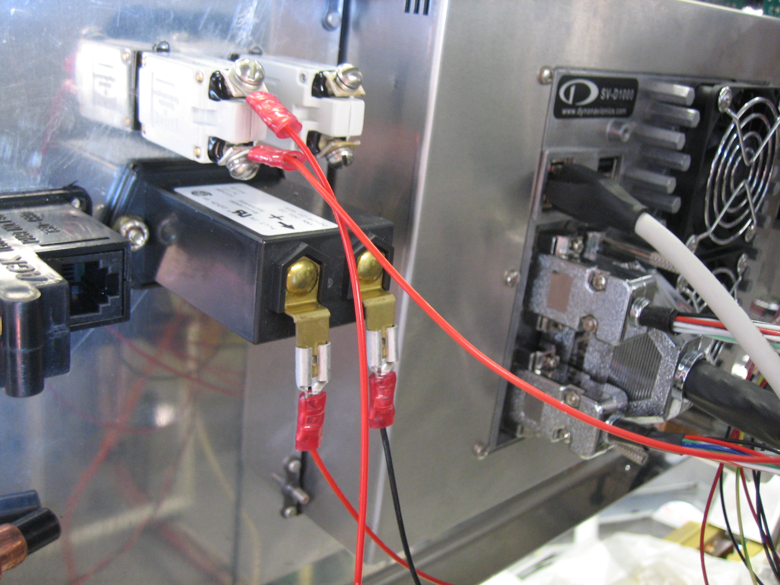
One of the last things to be wired through the isolation diodes was the autopilot servos. I wired them up through a pullable circuit breaker and then down to the wires under the seats. Afterward, I fired up the SkyView system and verified it could see the pitch servo. After a quick servo firmware update, I calibrated it temporarily and then verified the autopilot controlled it correctly.
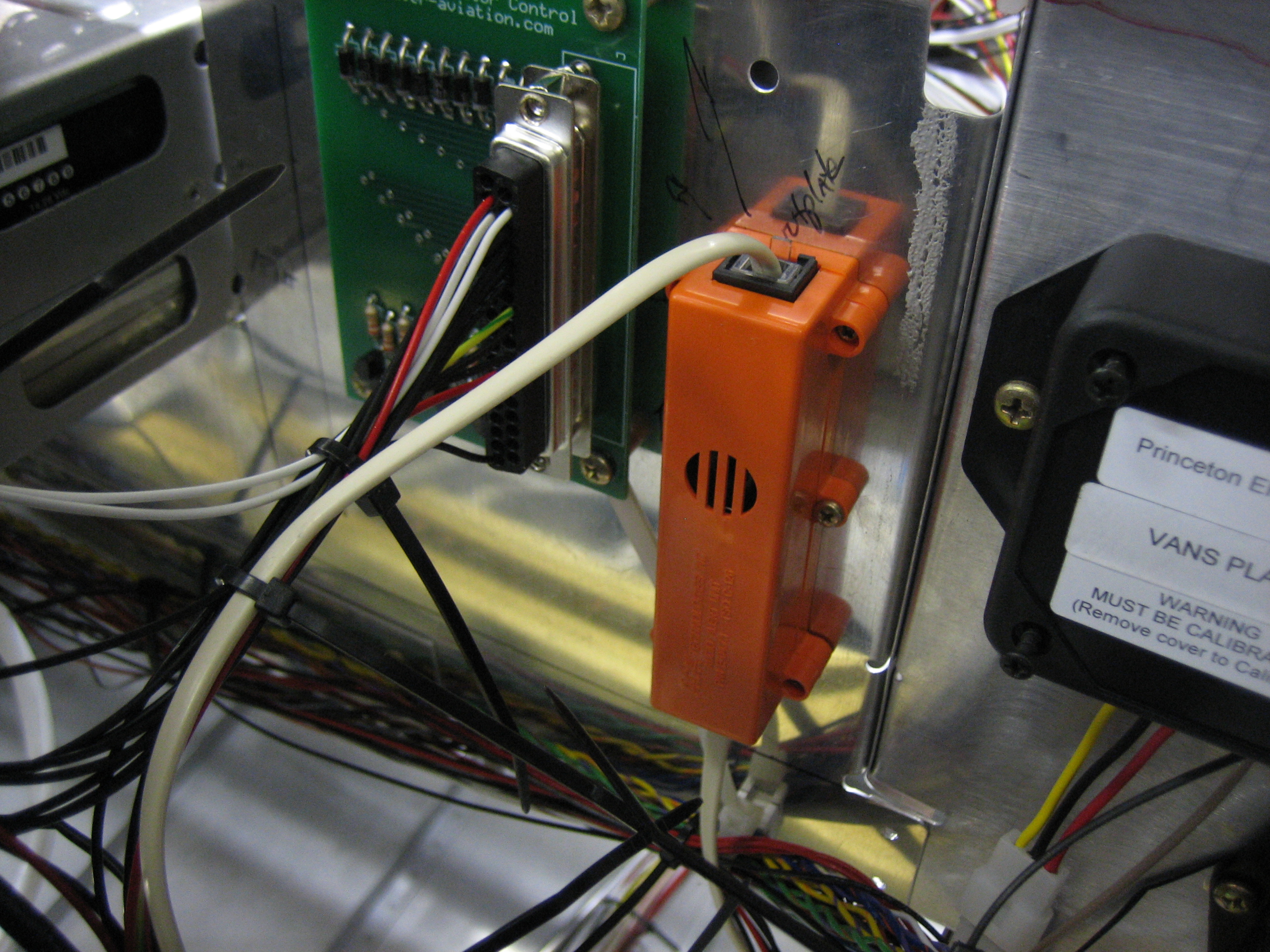
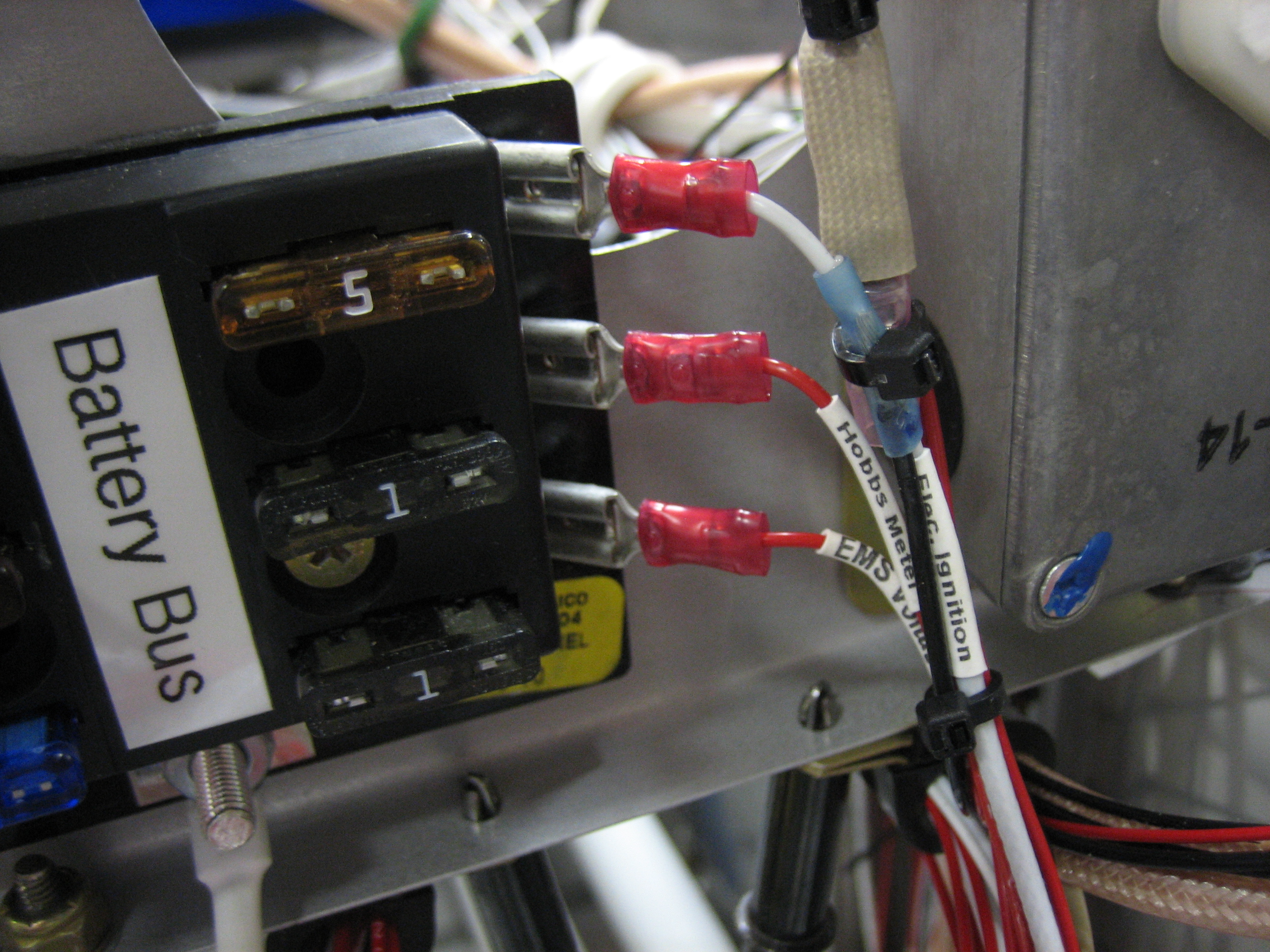
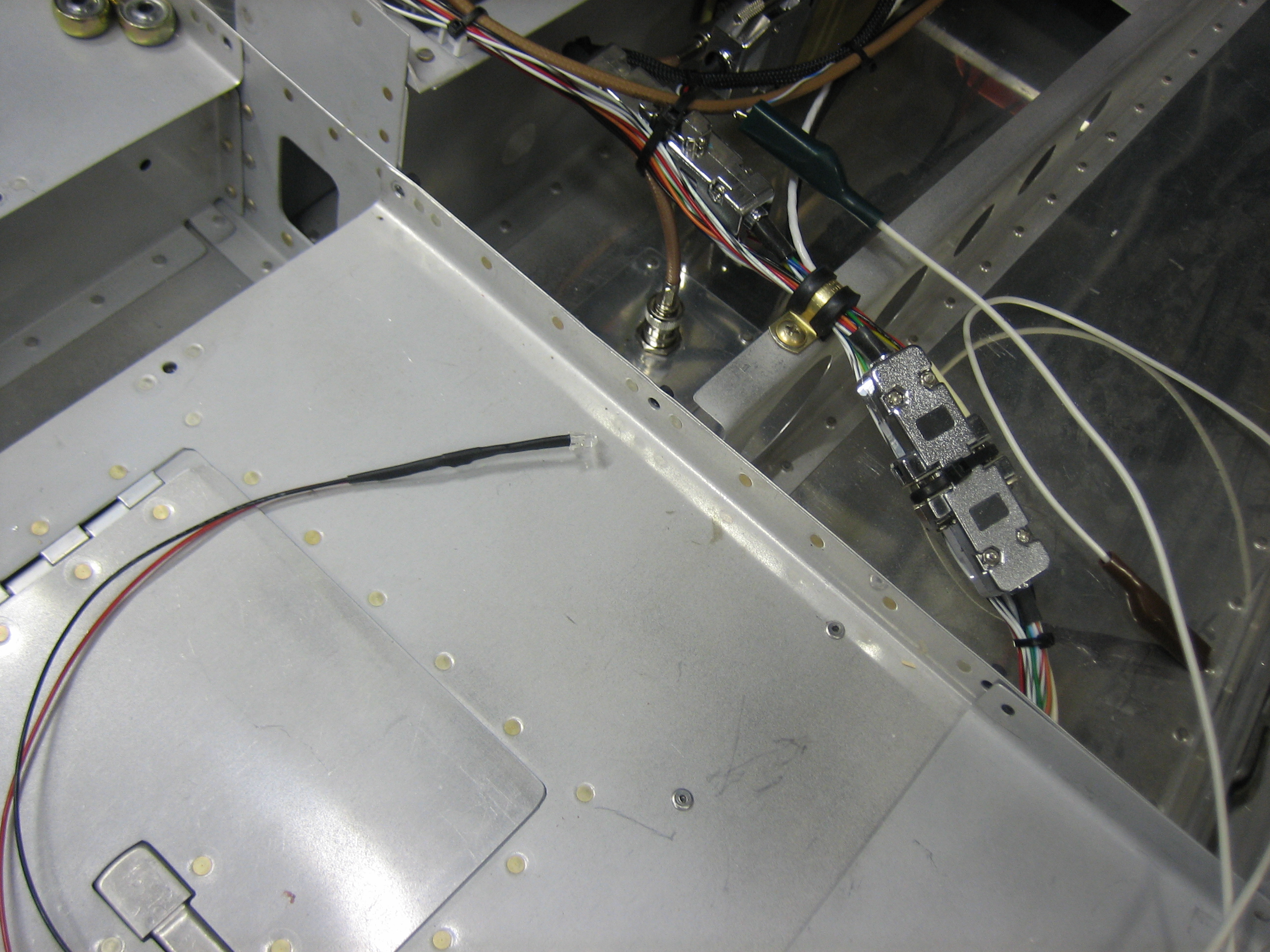
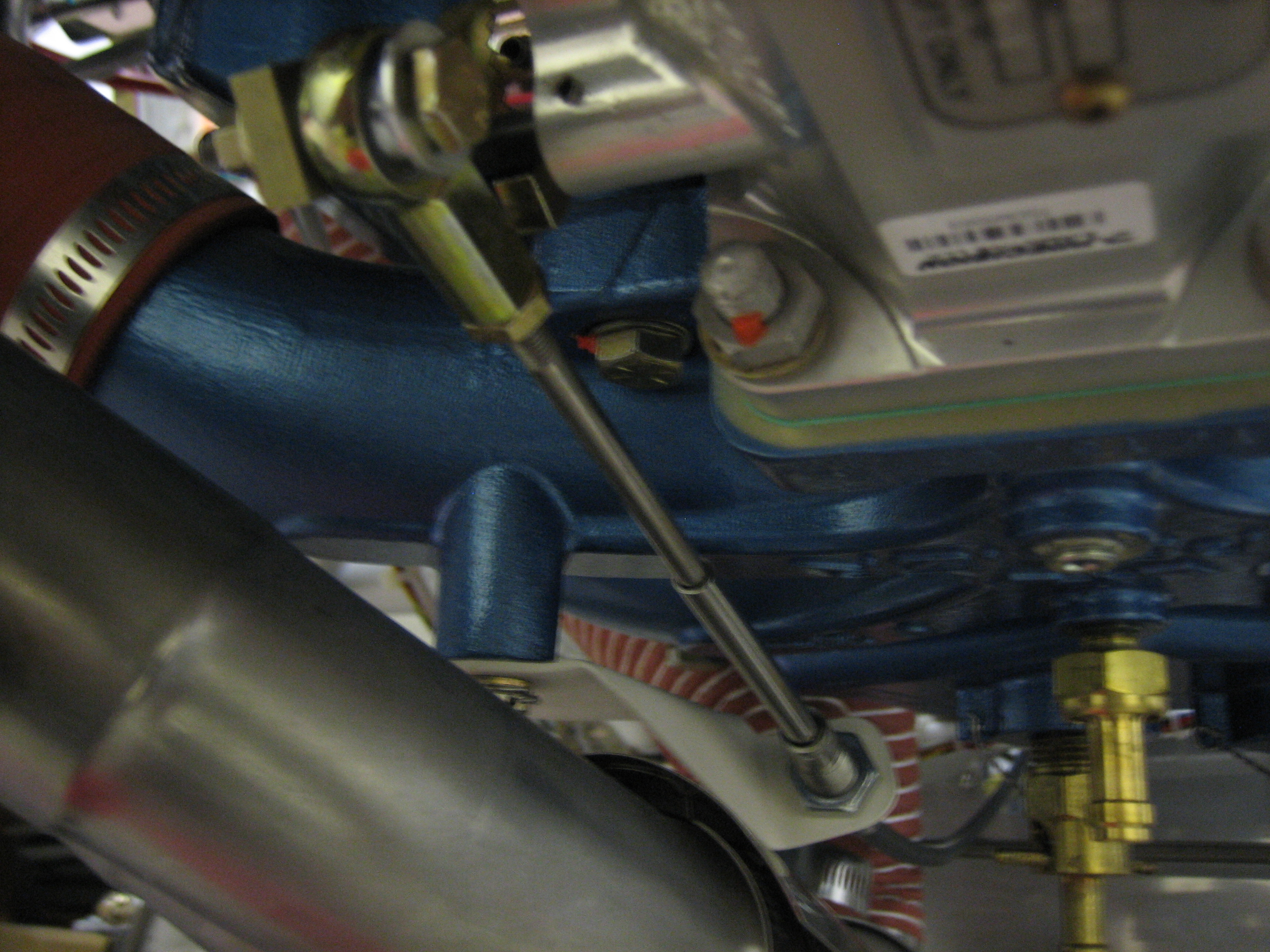
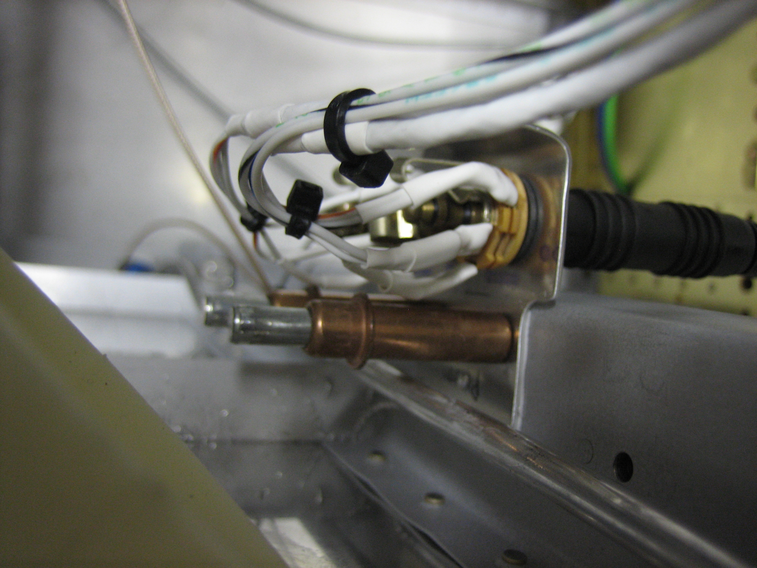
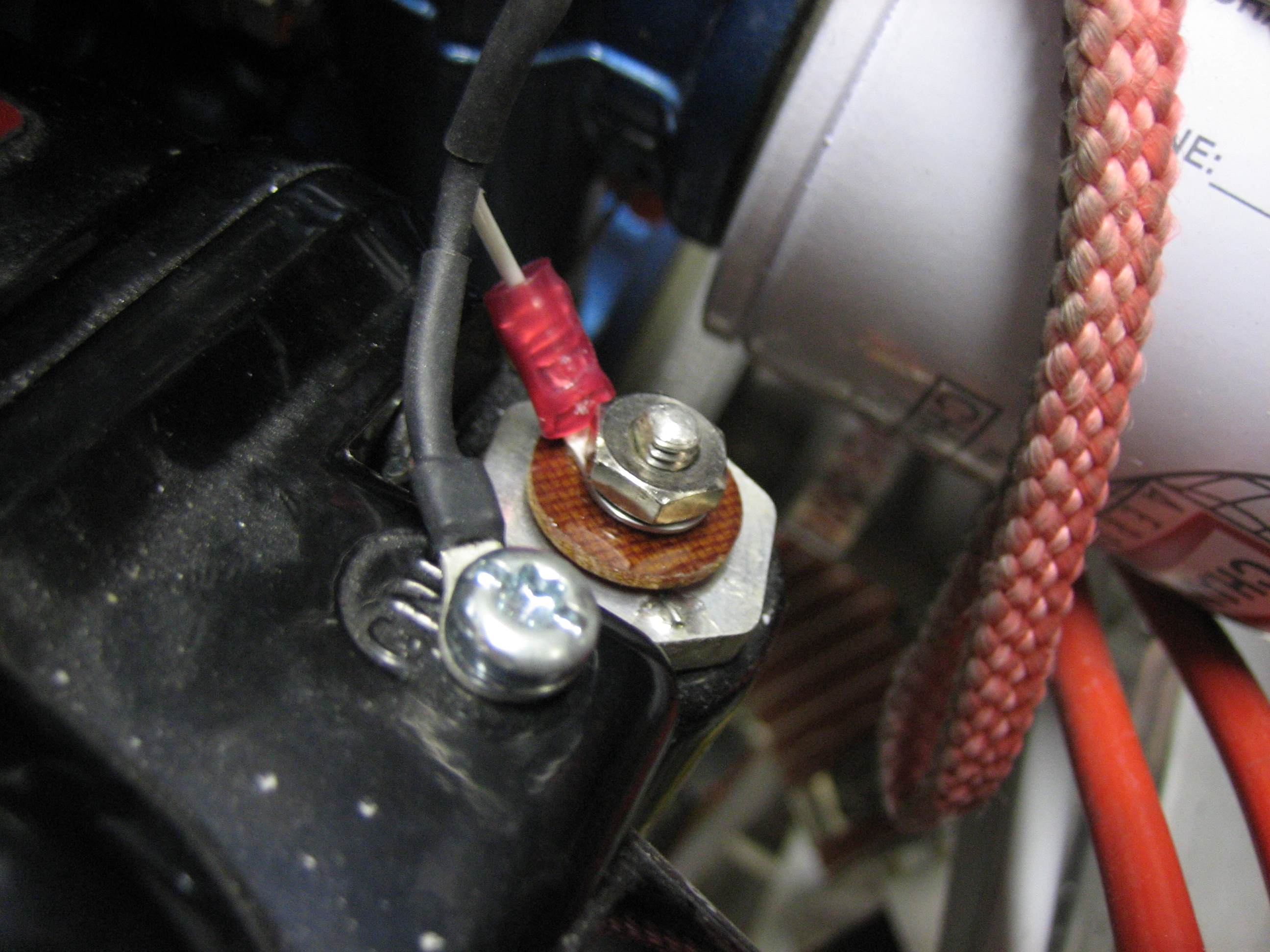
You can see here that I also wired up the hobbs meter. The positive side is wired to the battery bus and the negative side is wired to the normally open side of the oil pressure switch. I verified the current draw with an amp meter to determine the fuse size (1 amp is way more than enough).
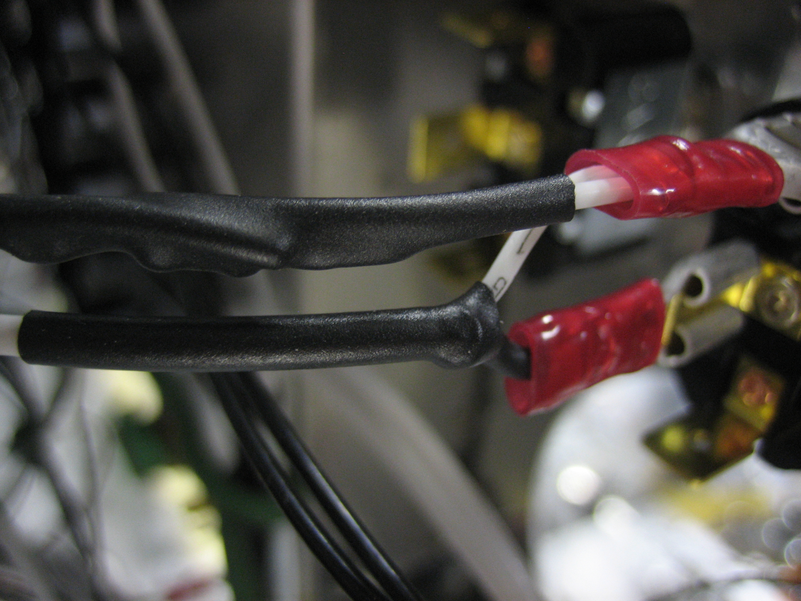
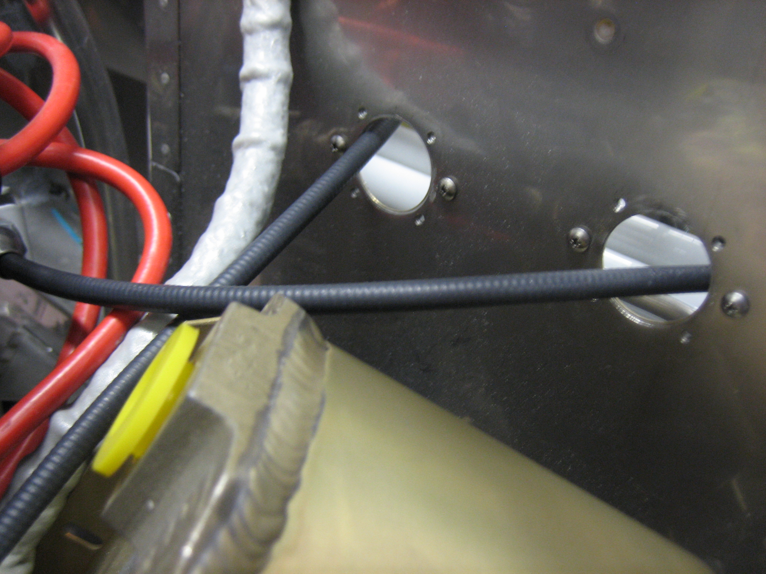
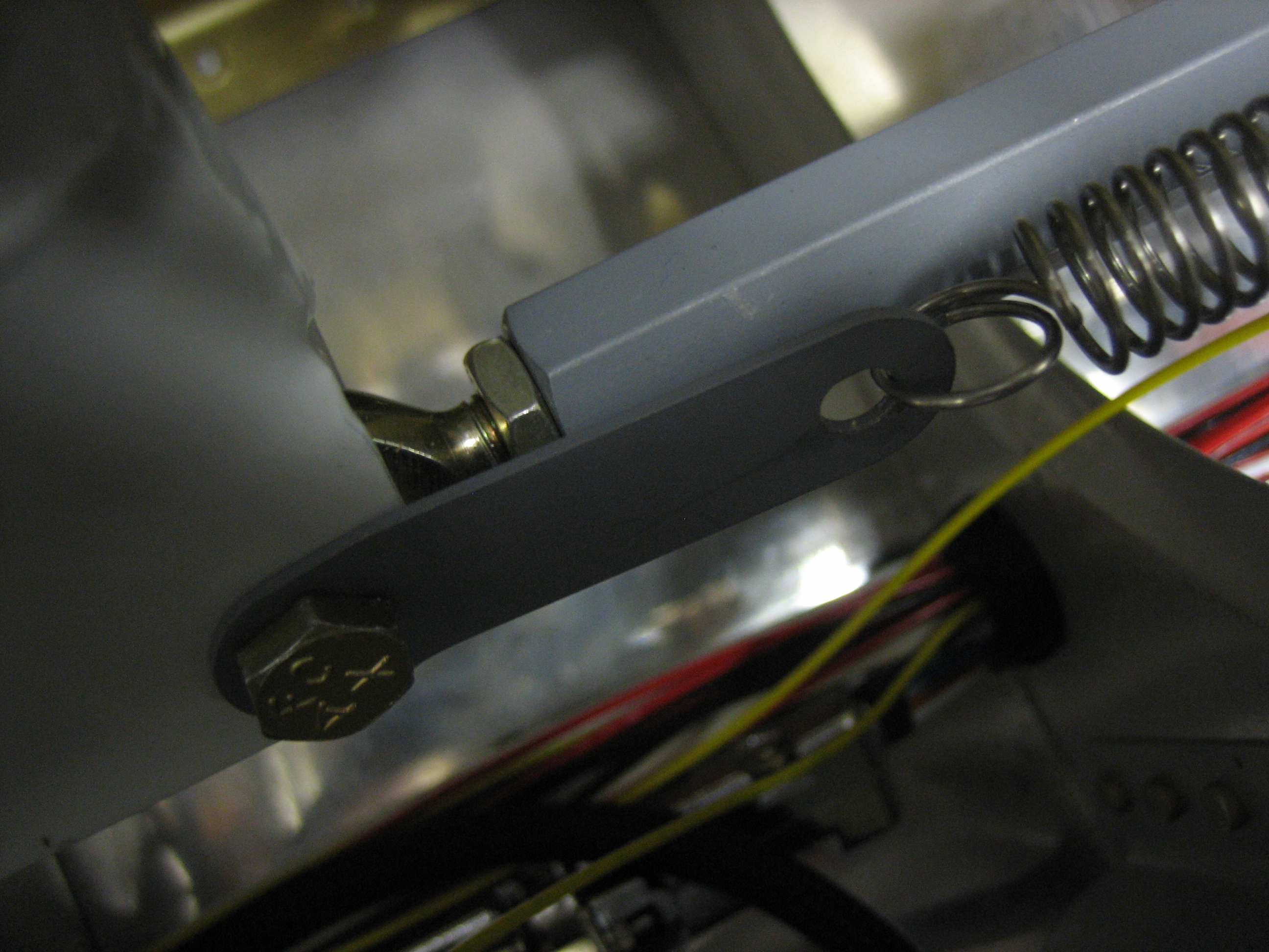
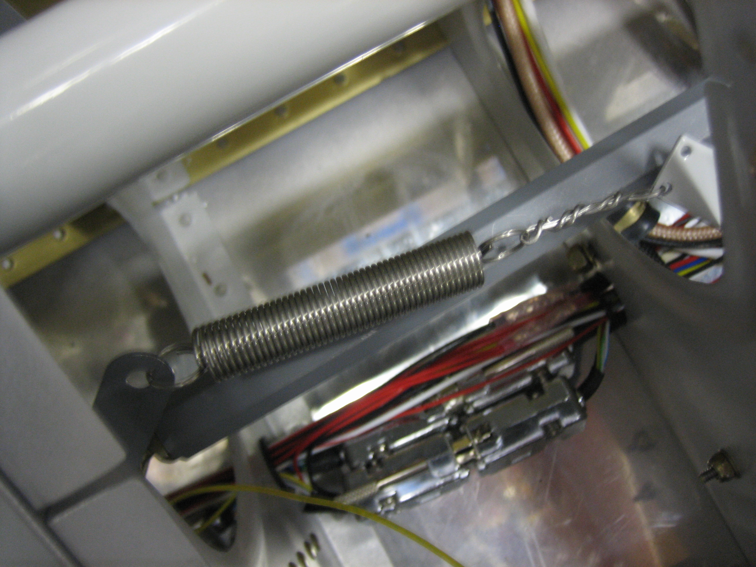
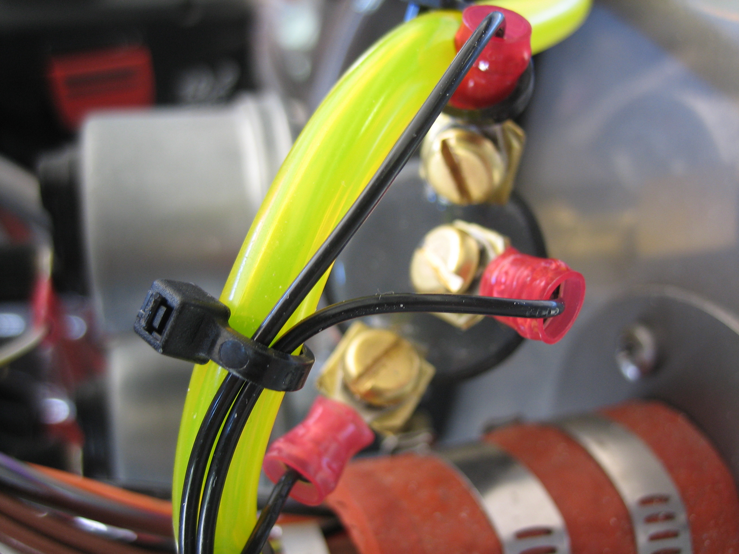
Here are the three wires to the oil pressure switch. The bottom wire is ground, the middle is the normally open contact to the hobbs switch, the top is the normally closed wire that runs to the annunciator control circuit. When the engine is running and oil pressure is applied, the switch closes which grounds the hobbs meter and starts it running while simultaneously opening the line to the annunciator control circuit which extinguishes the oil pressure light.
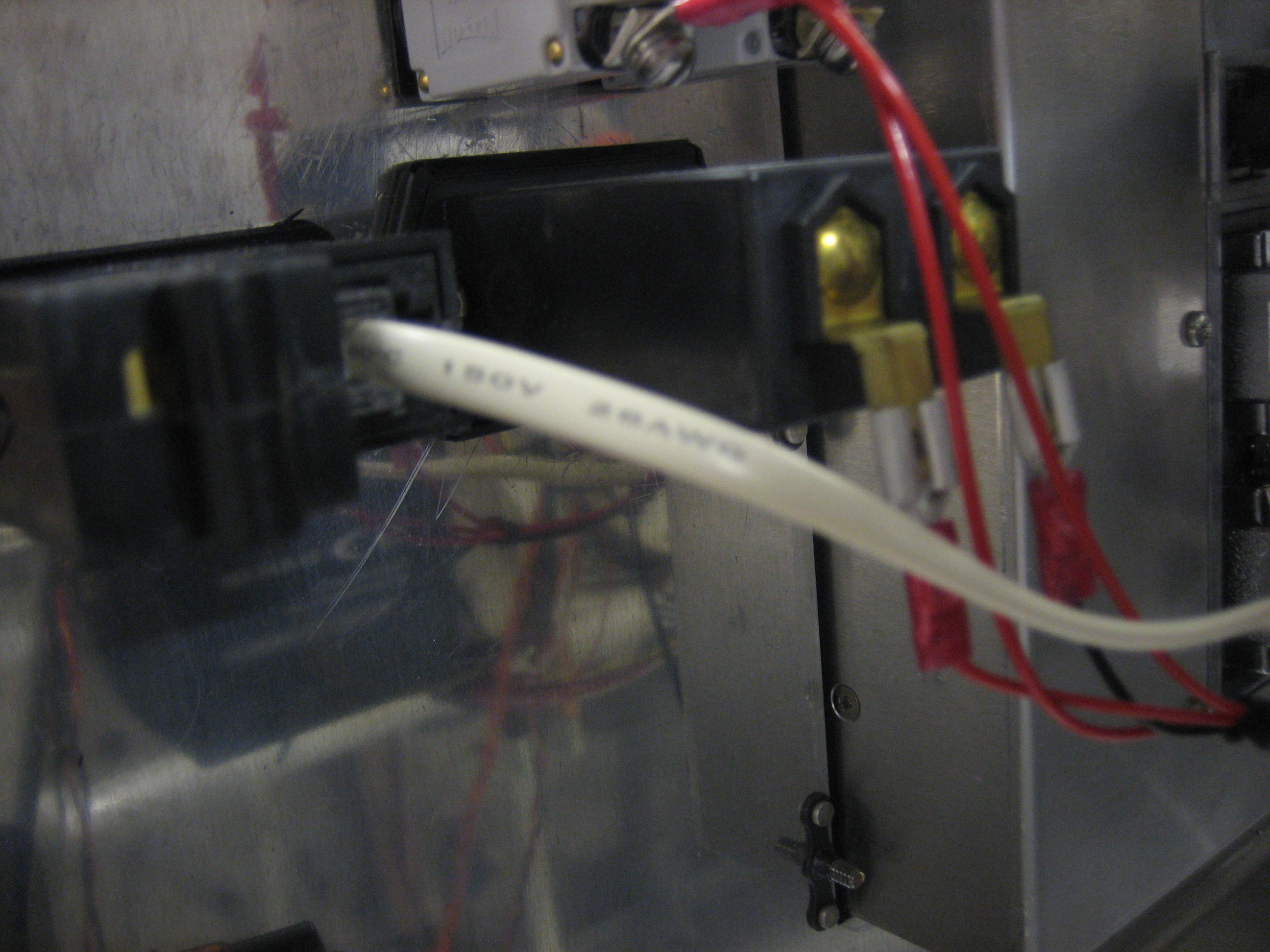
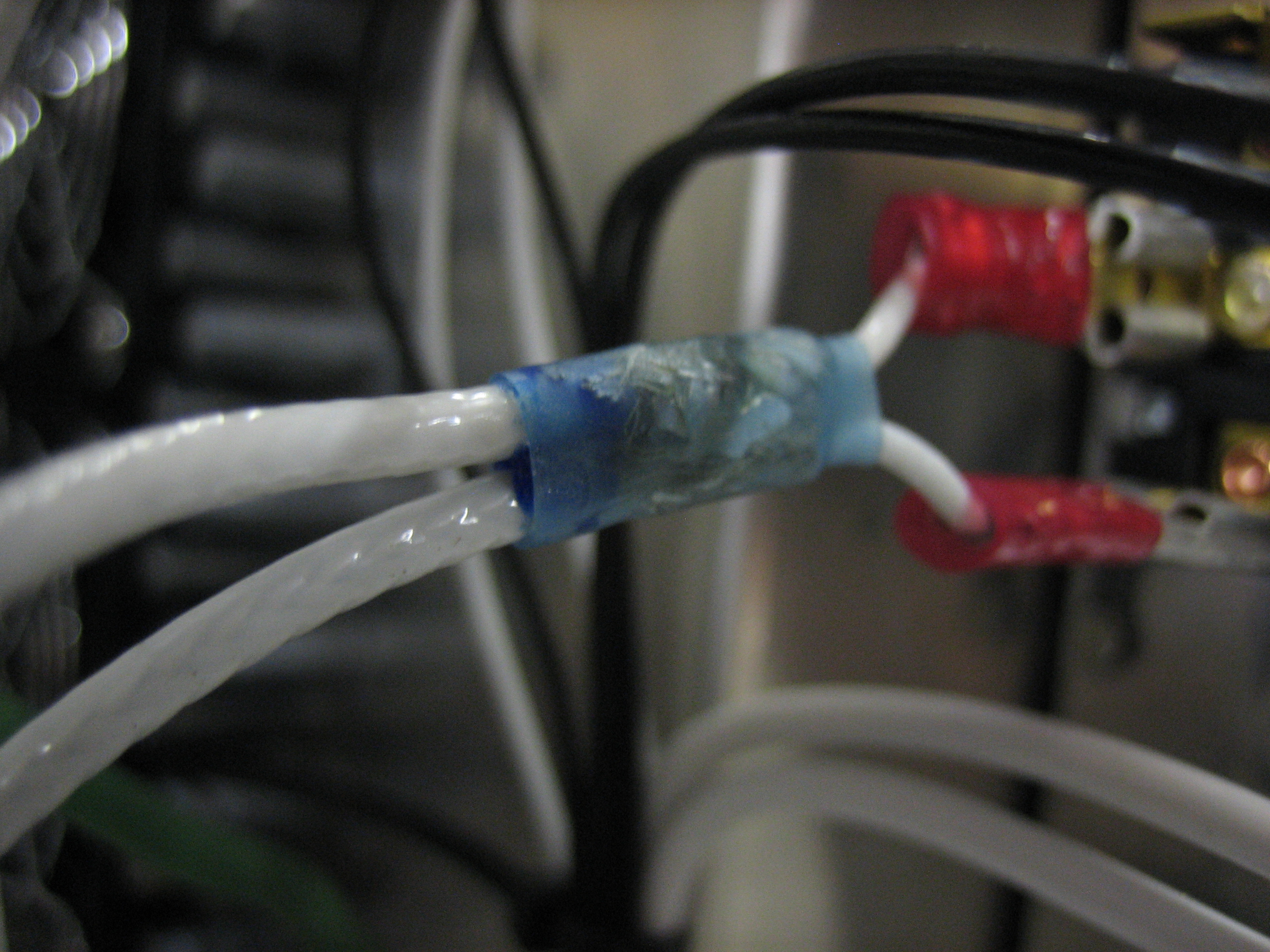
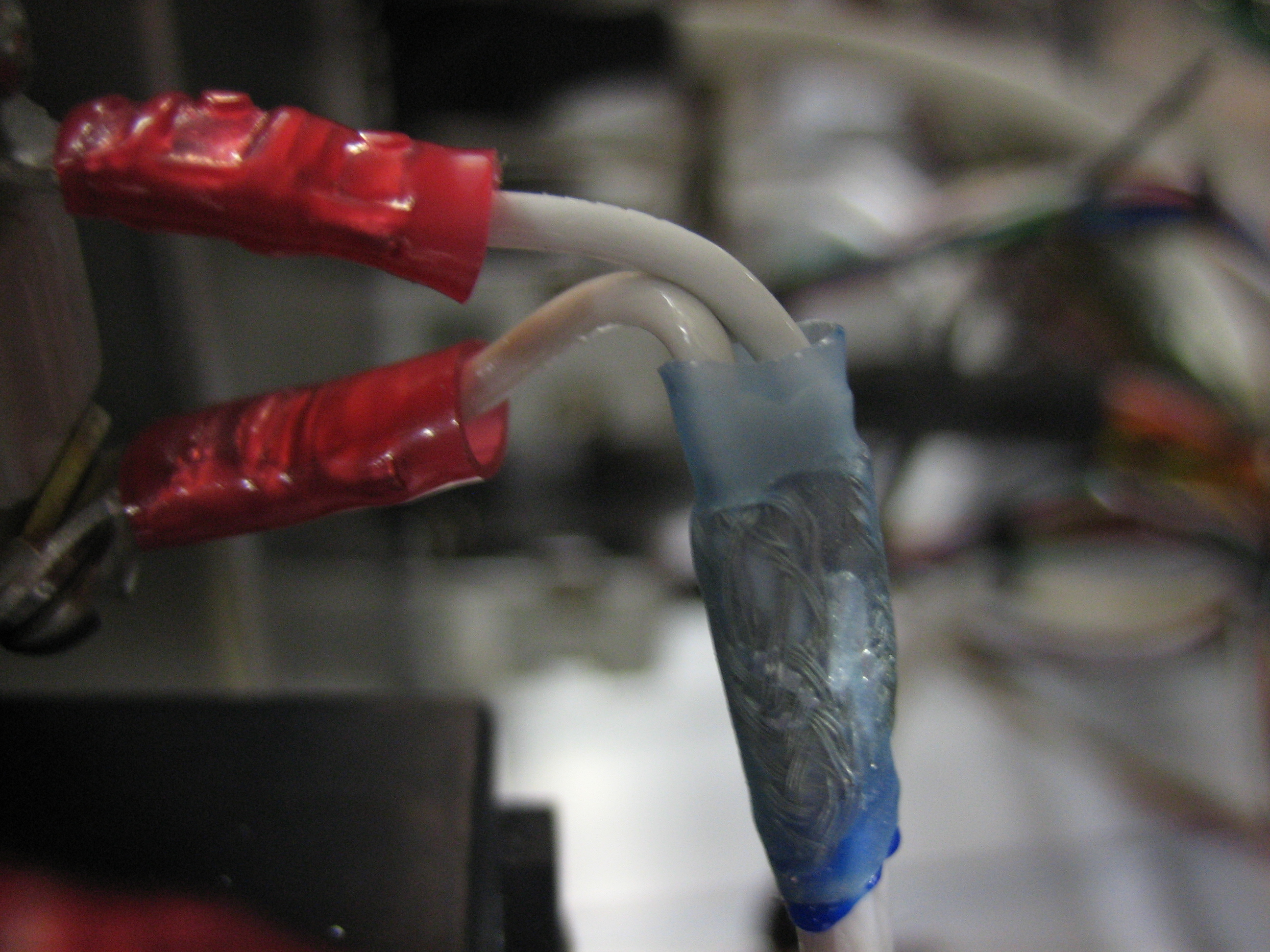
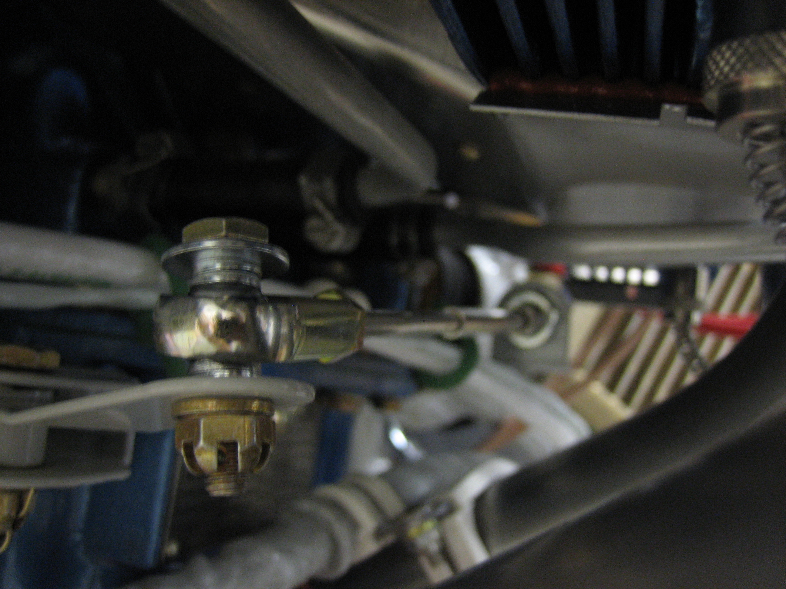
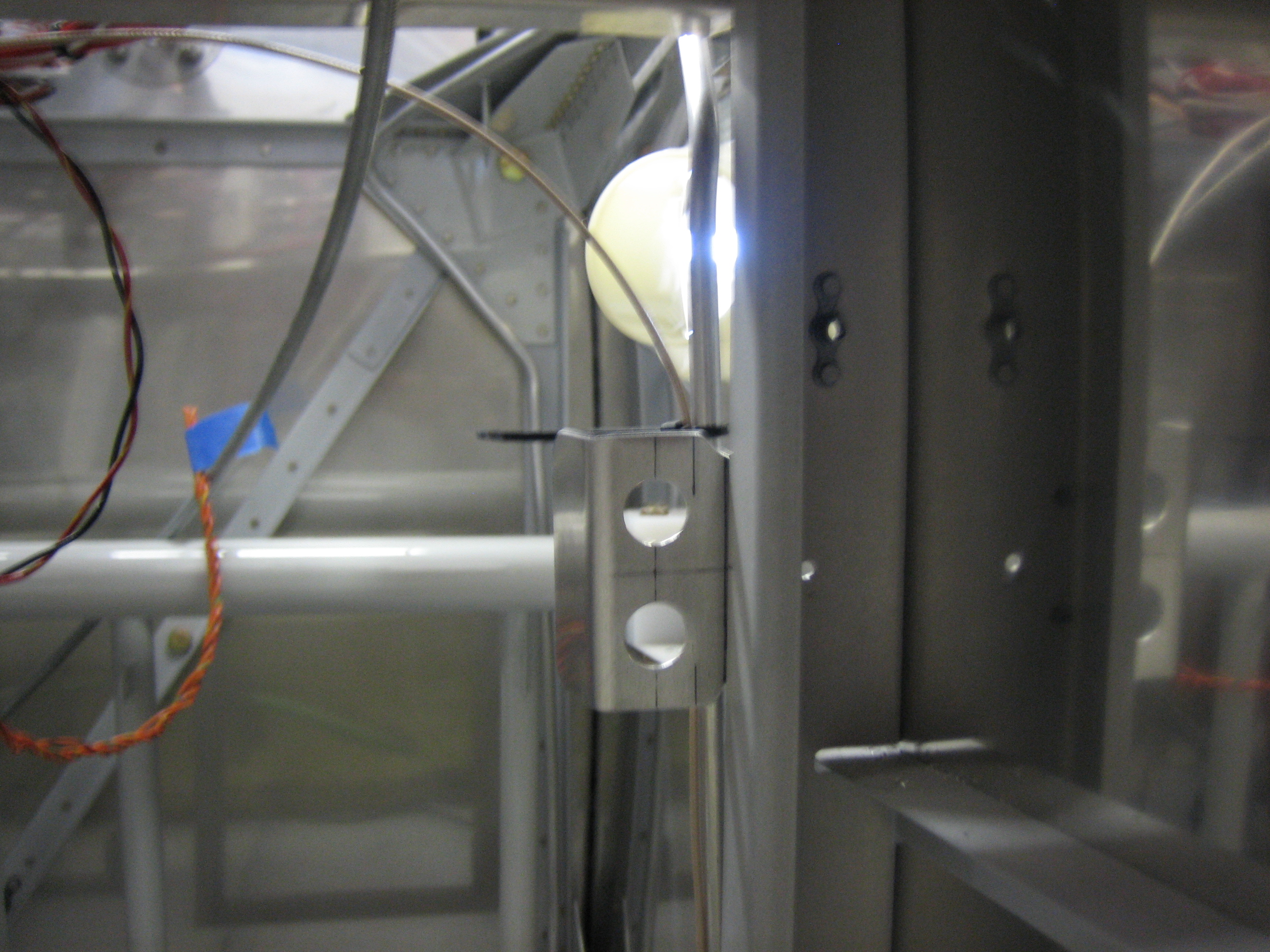
I also used some 20AWG shielded wire to connect up the mag switch. On the mag end, the center conductor is connected to the far post, while the shield is split off and wired to the ground post on the mag. I little heat shrink keeps everything tidy.
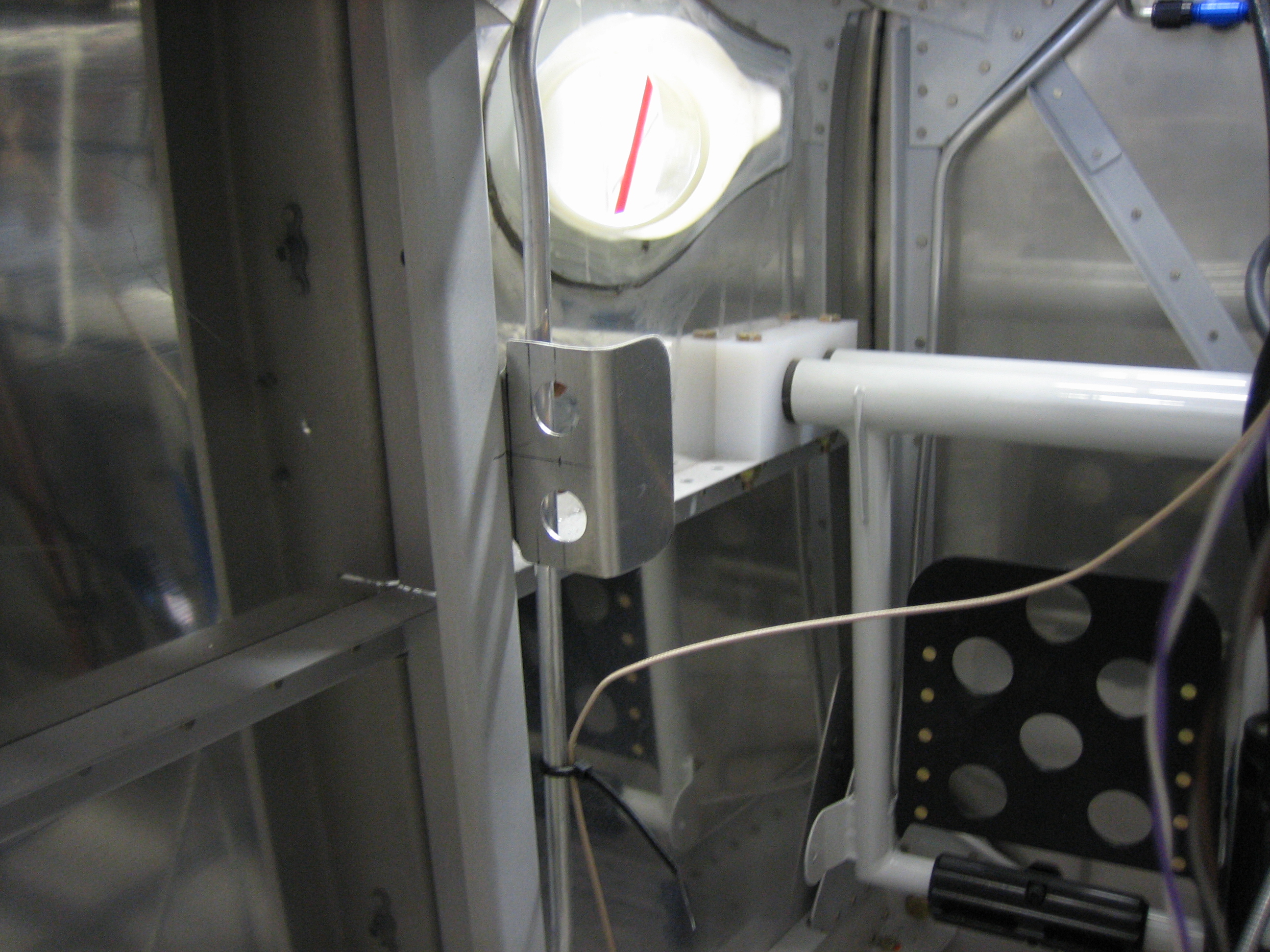
On the switch end, the shielded wire comes in on the bottom and has a similar split, The center conductor is also connected to a tap wire that includes a 30k? resistor. This wire goes to the SkyView EMS to provide RPM indication. The Lightspeed ignition also provides RPM indication, so the SkyView has redundant sources for this info.