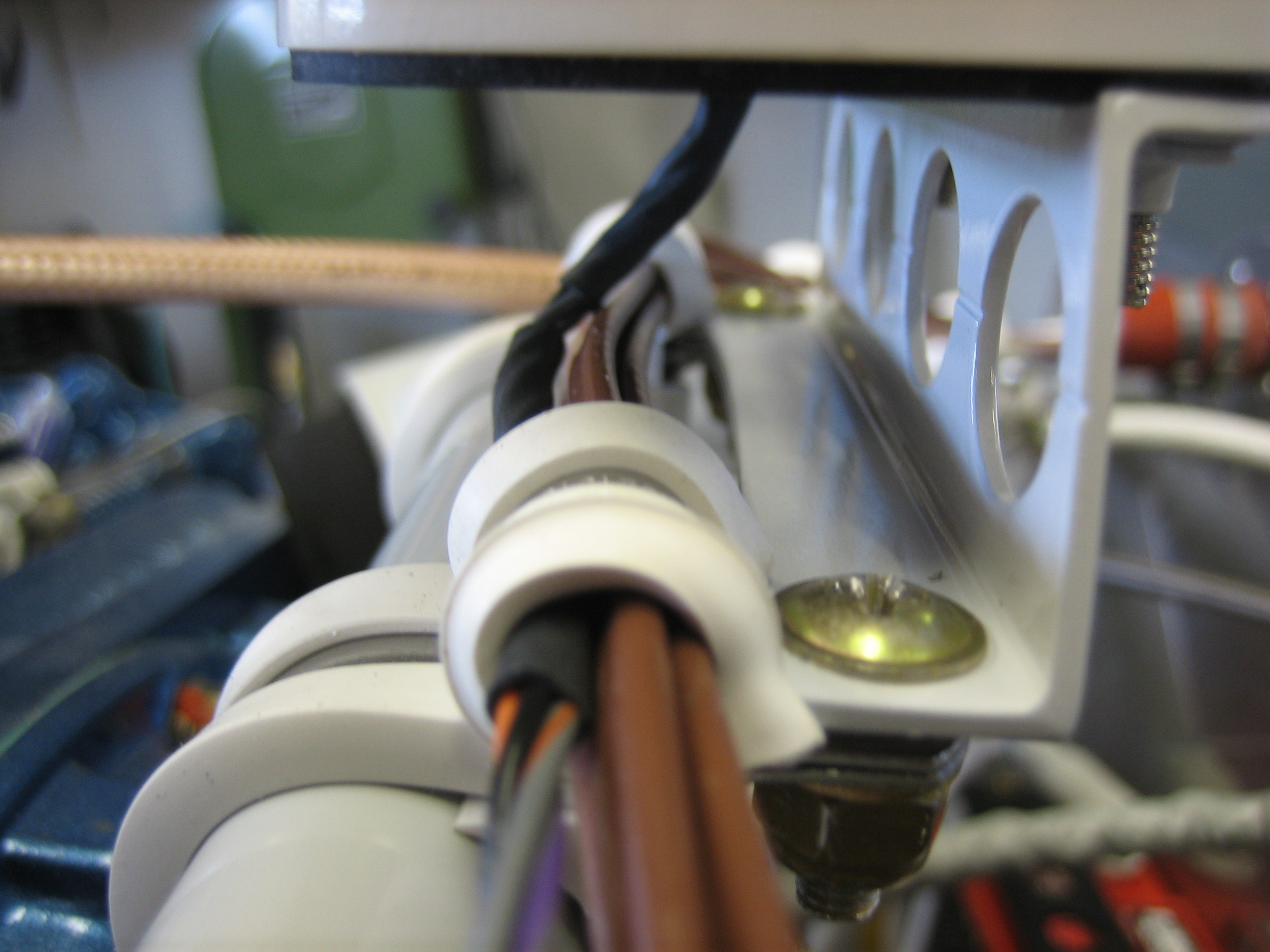
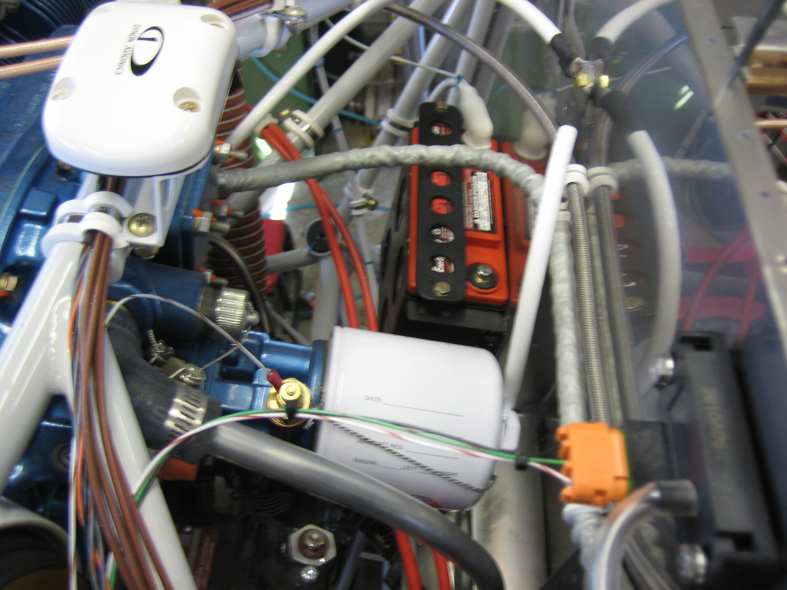
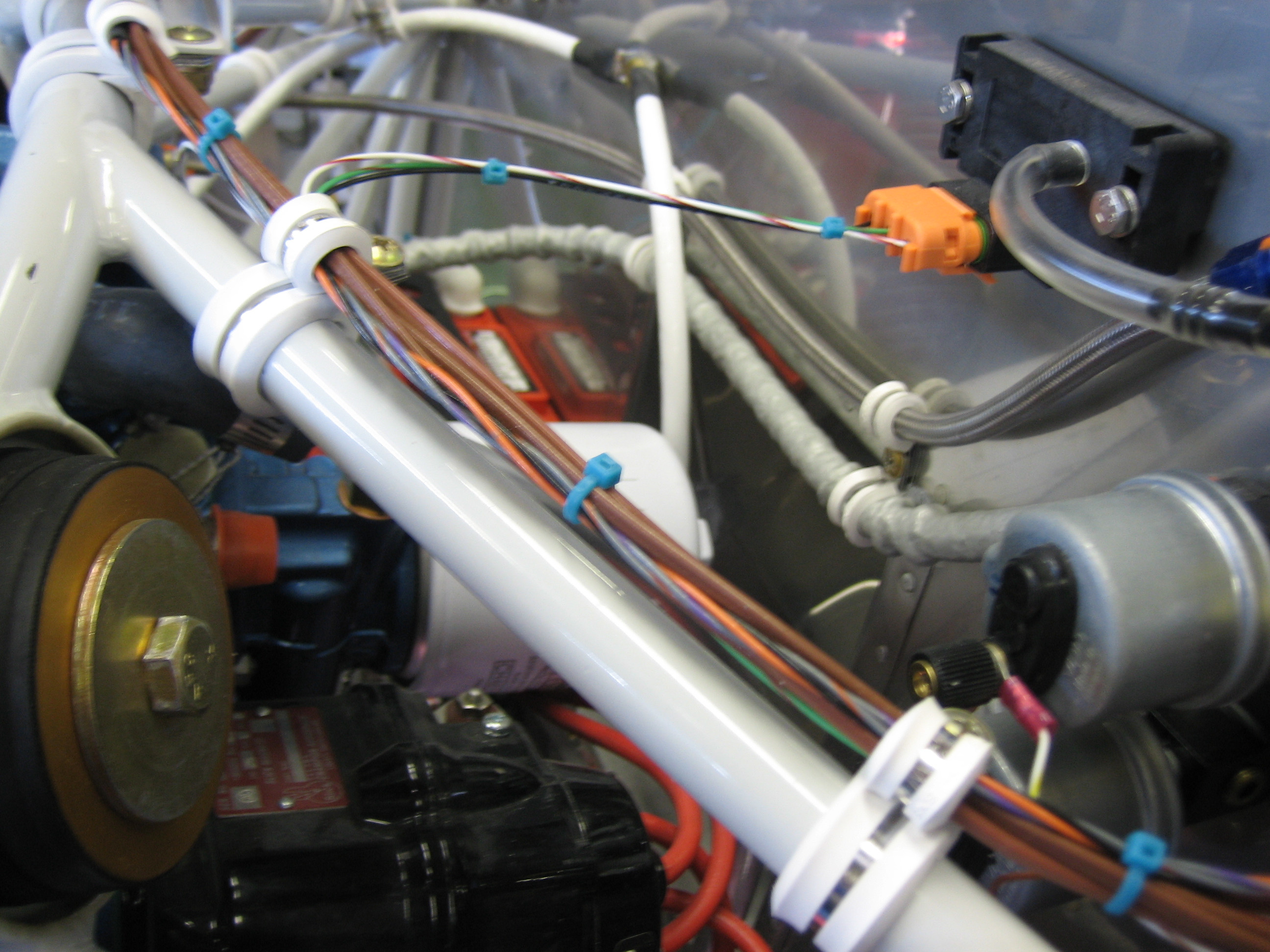
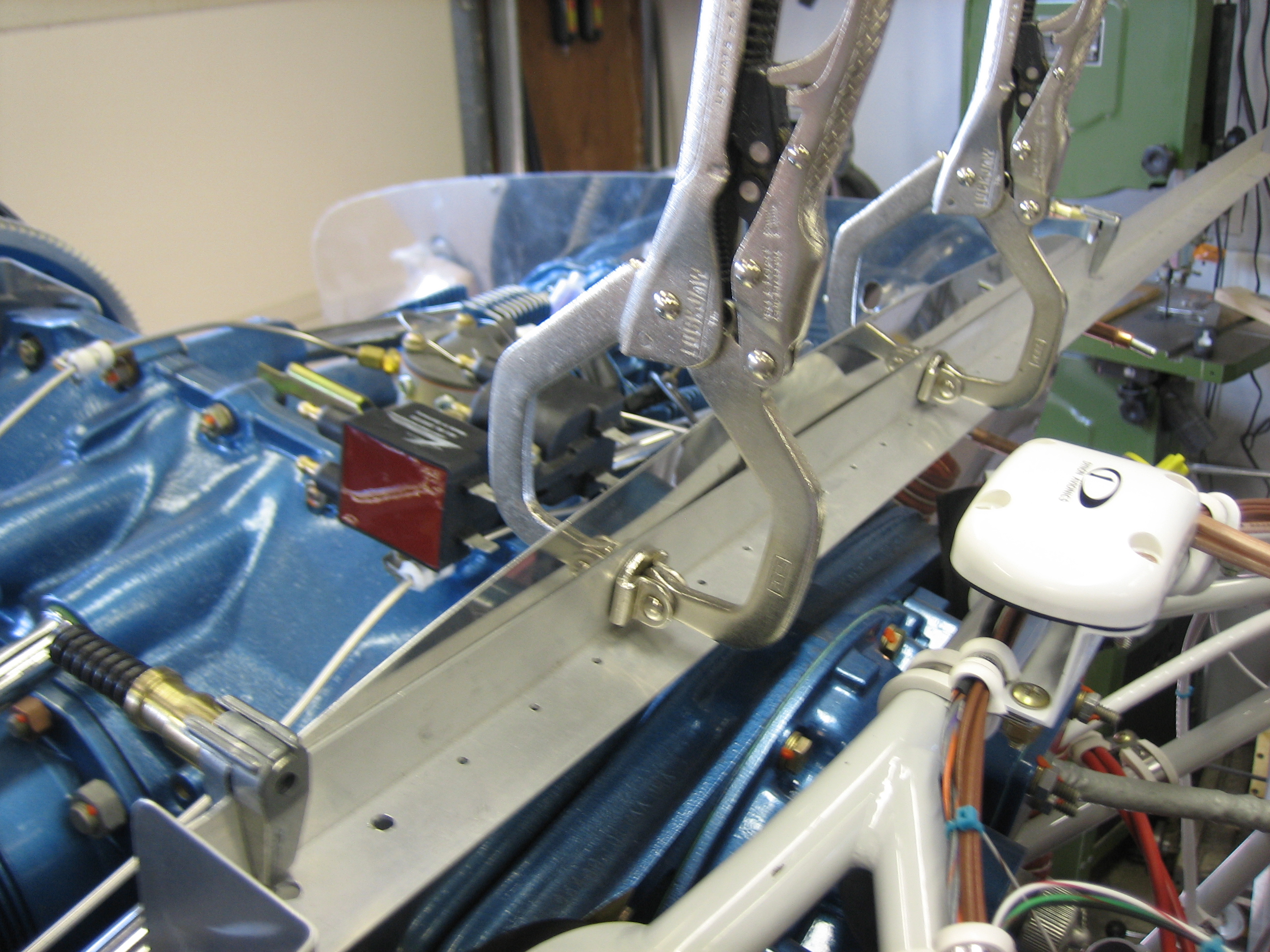
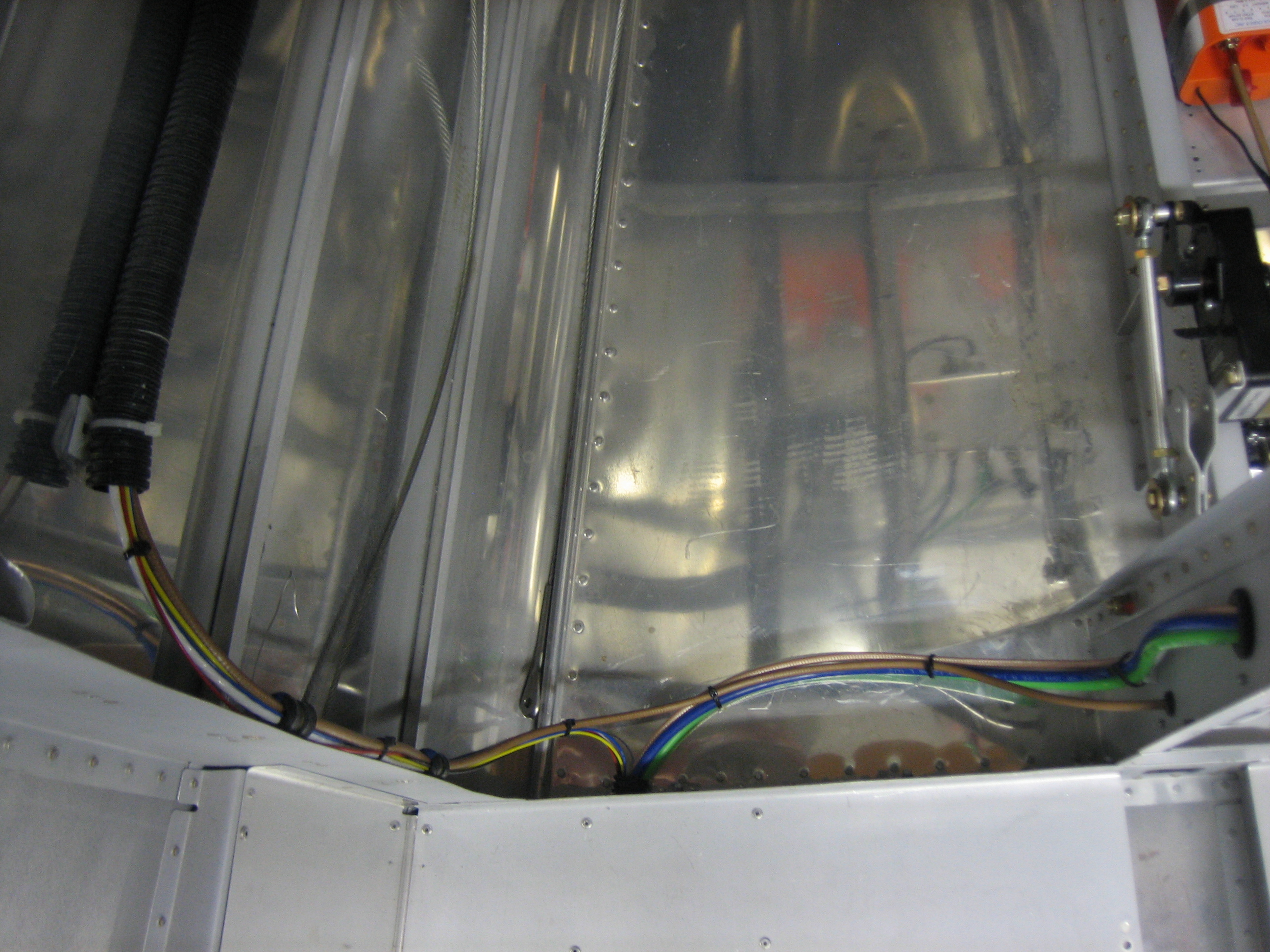
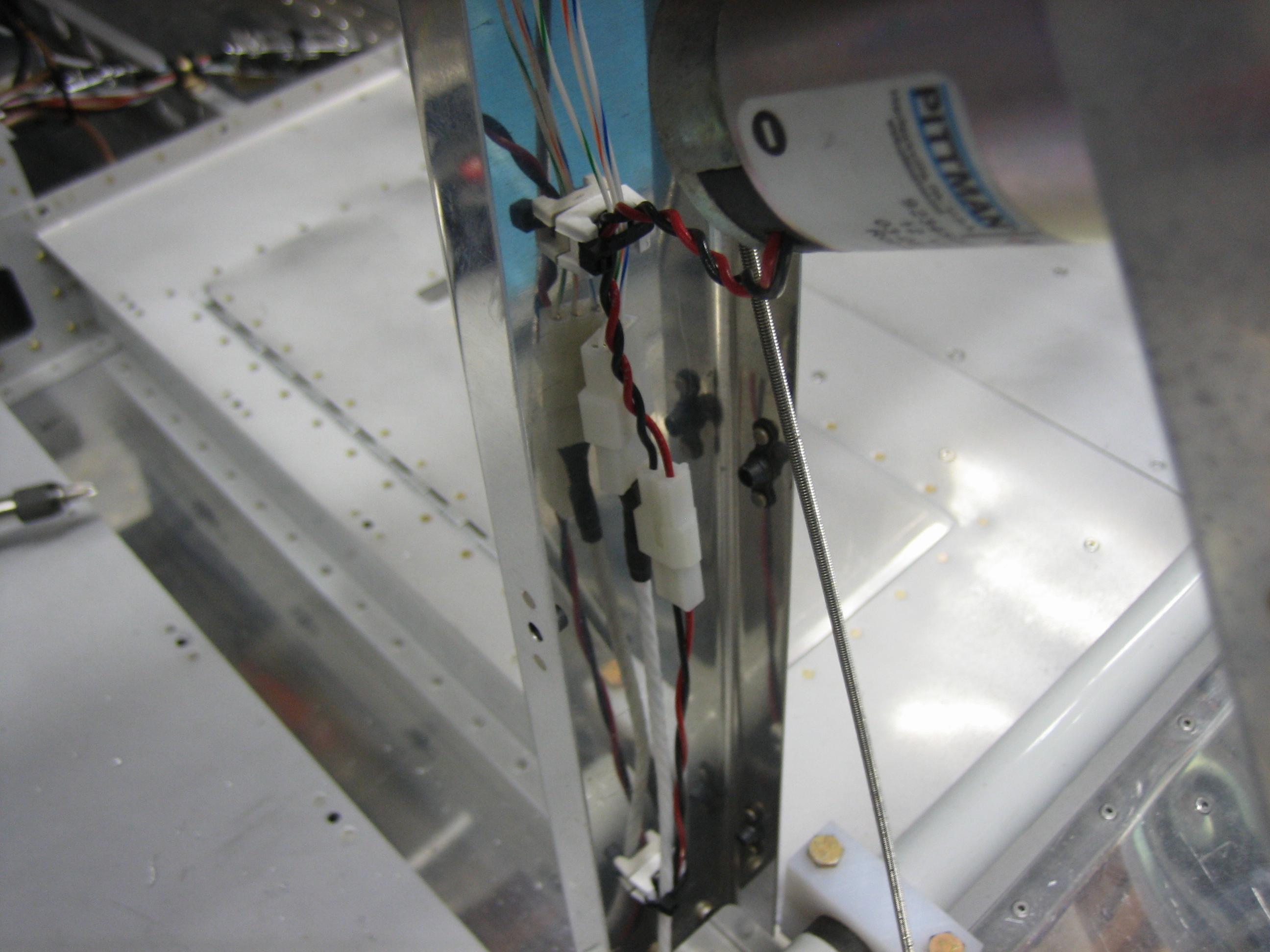
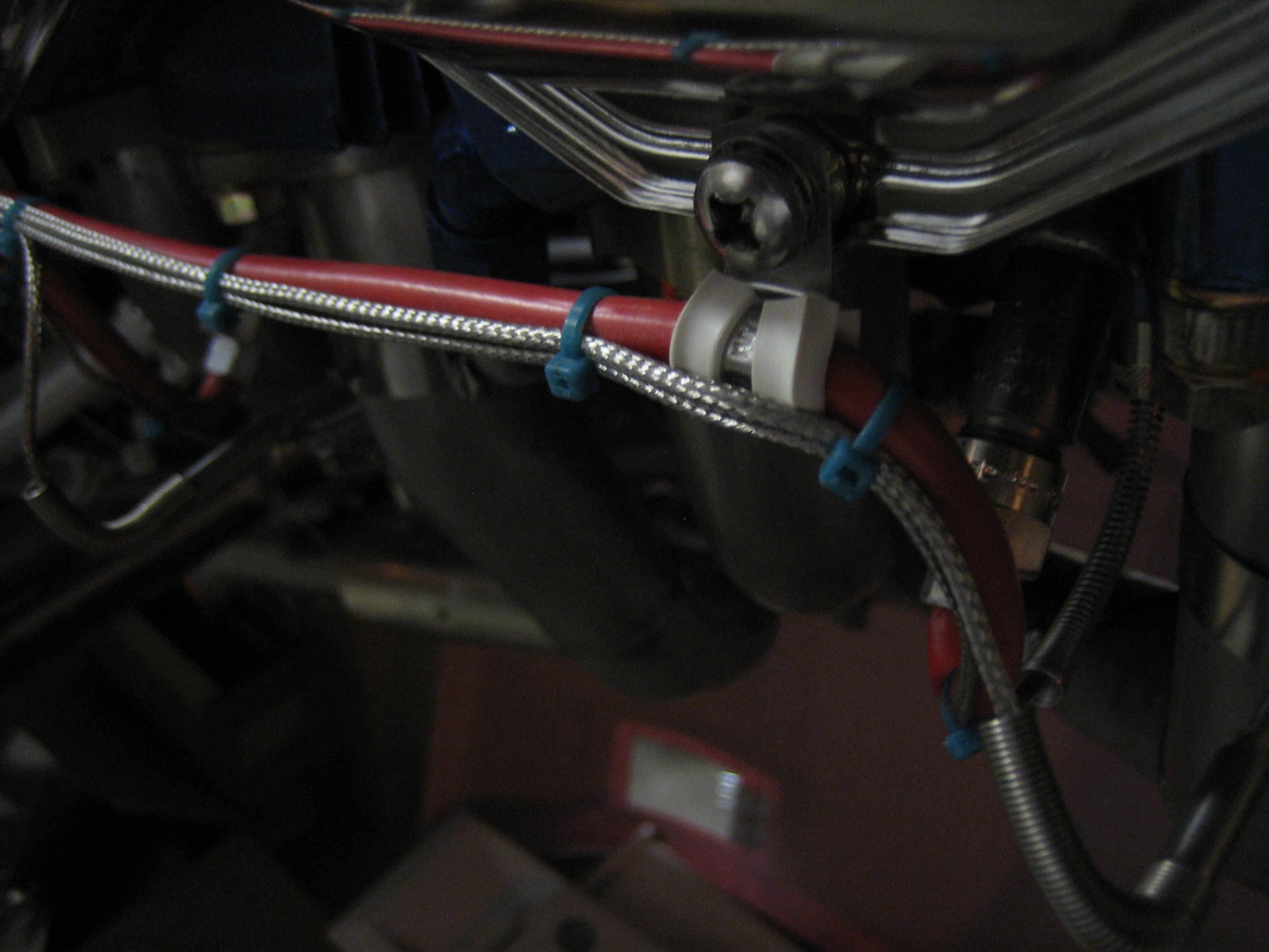
I got an order from McMaster Carr that included some more silicone adel clamps along with some tefzel zip-ties. I installed a few to secure all of the wires near the right firewall pass-through.
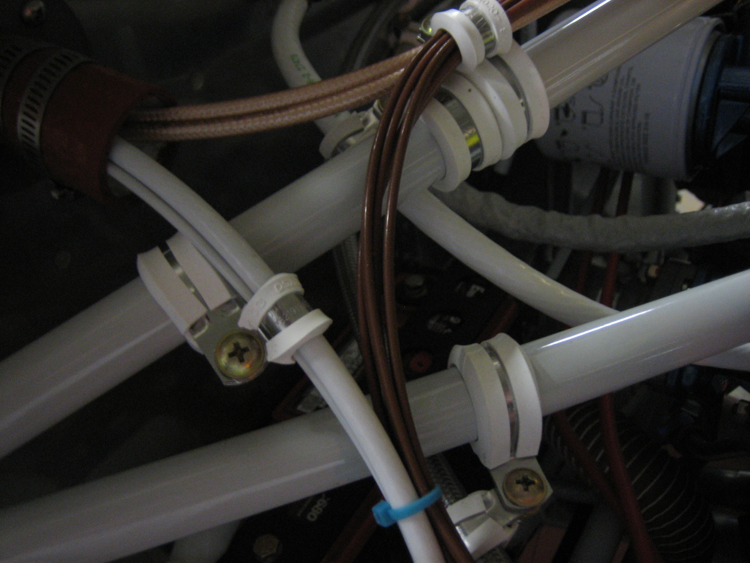
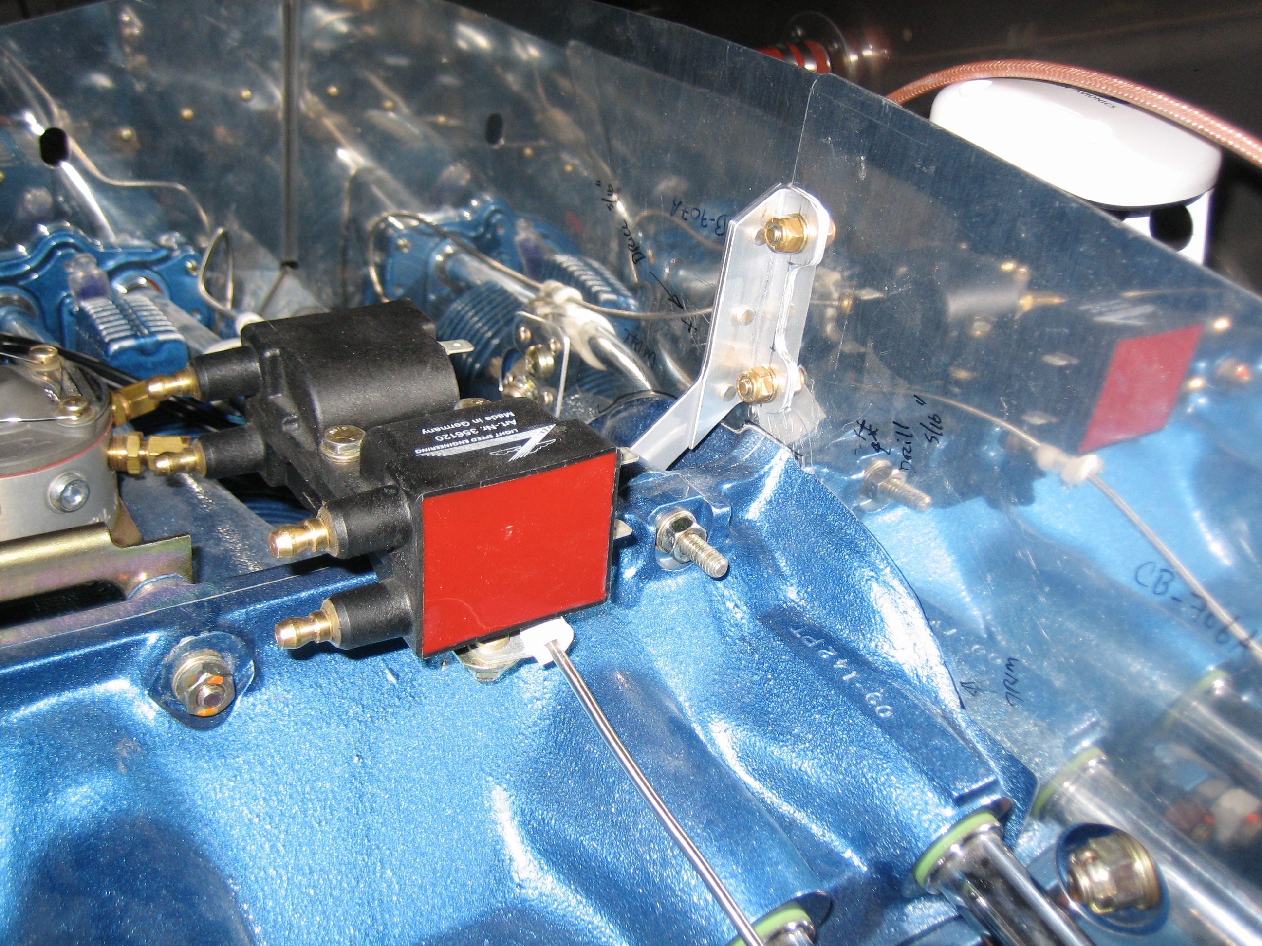
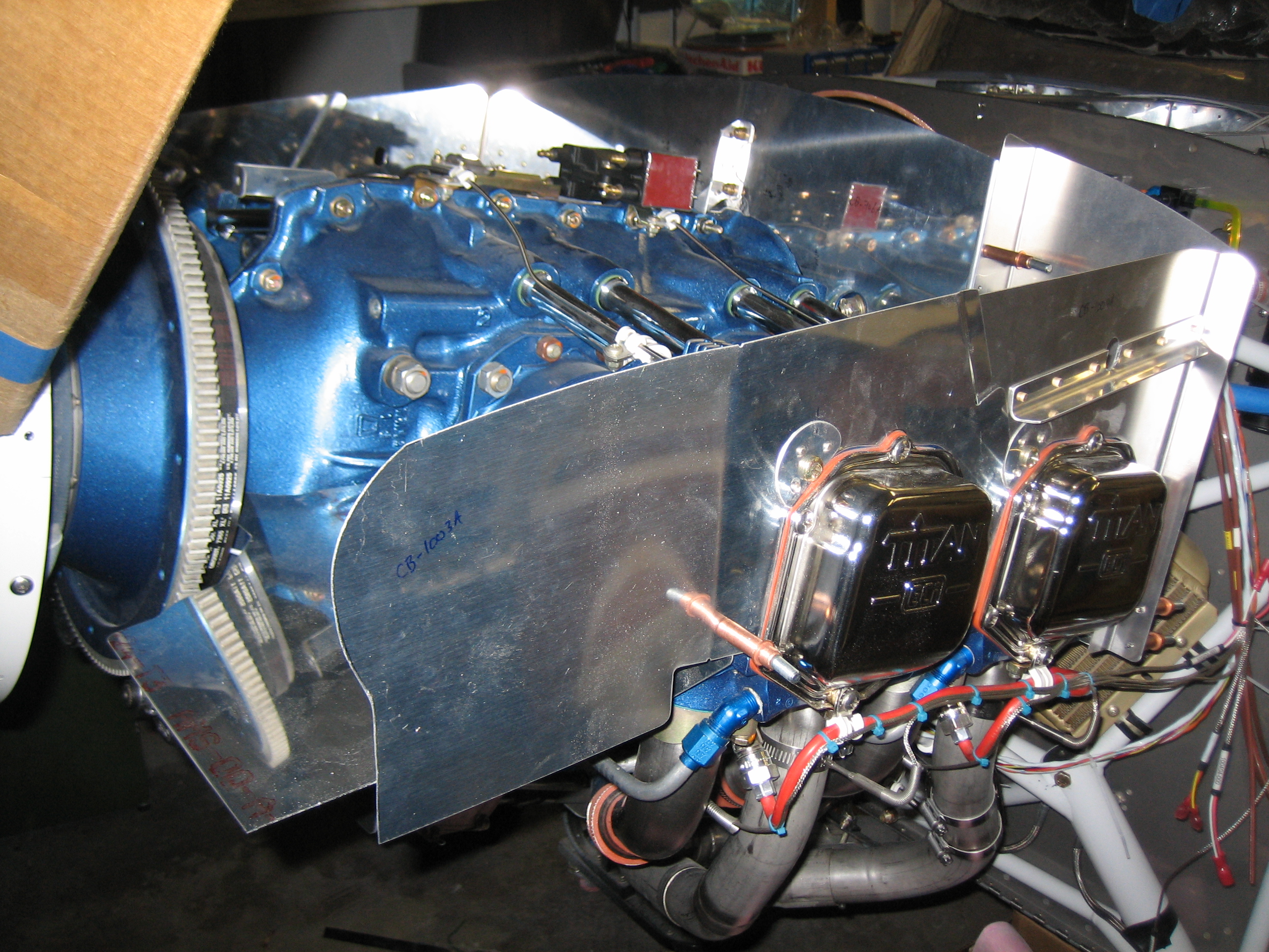
This nicely tidied up the EGT, CHT, and Lightspeed Ignition wires running across the upper engine mount tube.
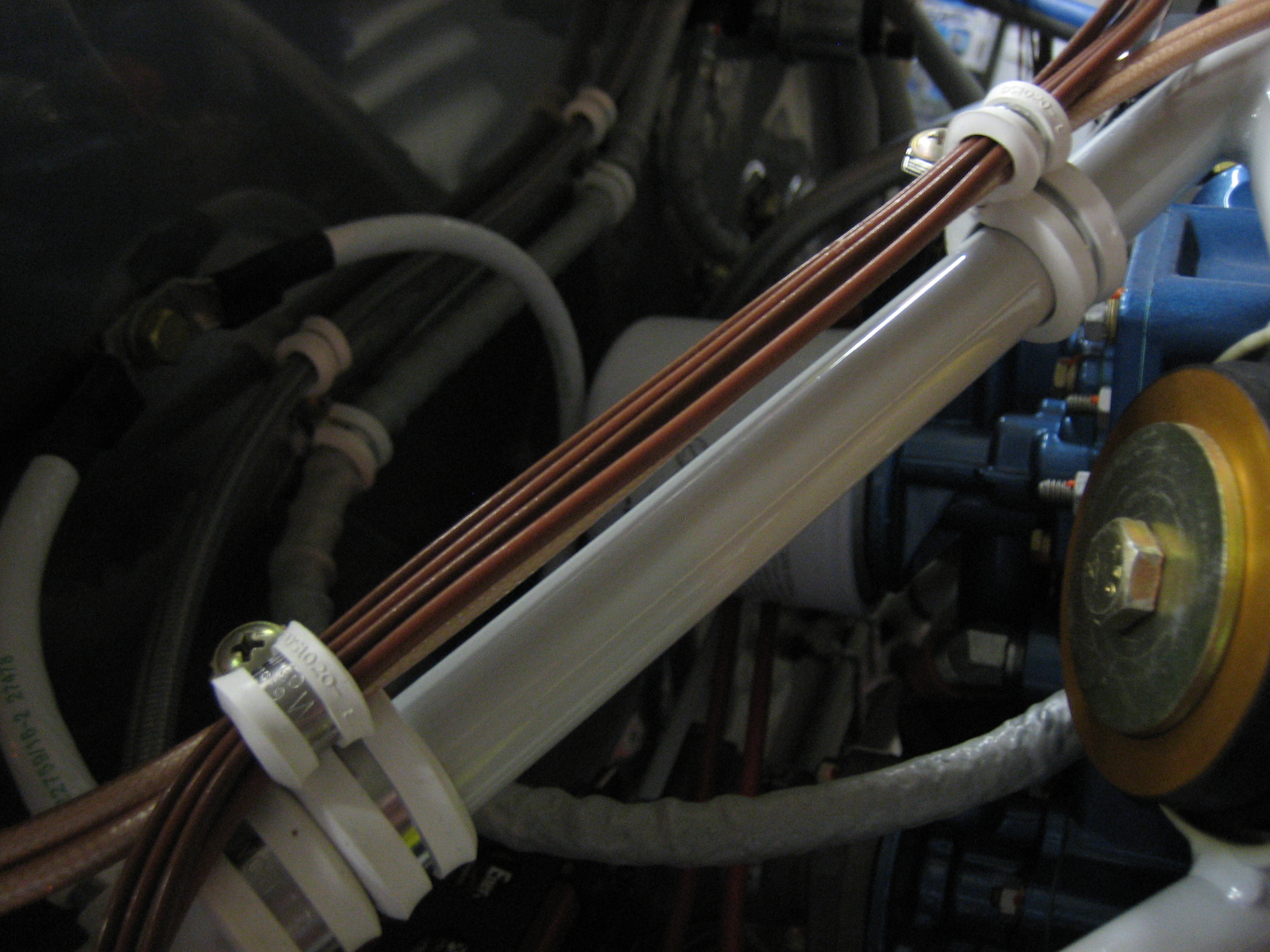
I also replaced a bunch of the temporary nylon zip-ties with the tefzel. Regular nylon zip-ties are only good up to about 185º F. Black, UV stabilized zip-ties are better at up to 221º F, but tefzel is good up to 300º F. There are even higher rated zip-ties such as PEEK which is good to 500º F, but they’re over $3 per zip-tie! All of the wire insulation in the plane is also tefzel insulated, so if it’s hot enough that these zip-ties melt, I’ll have other problems.
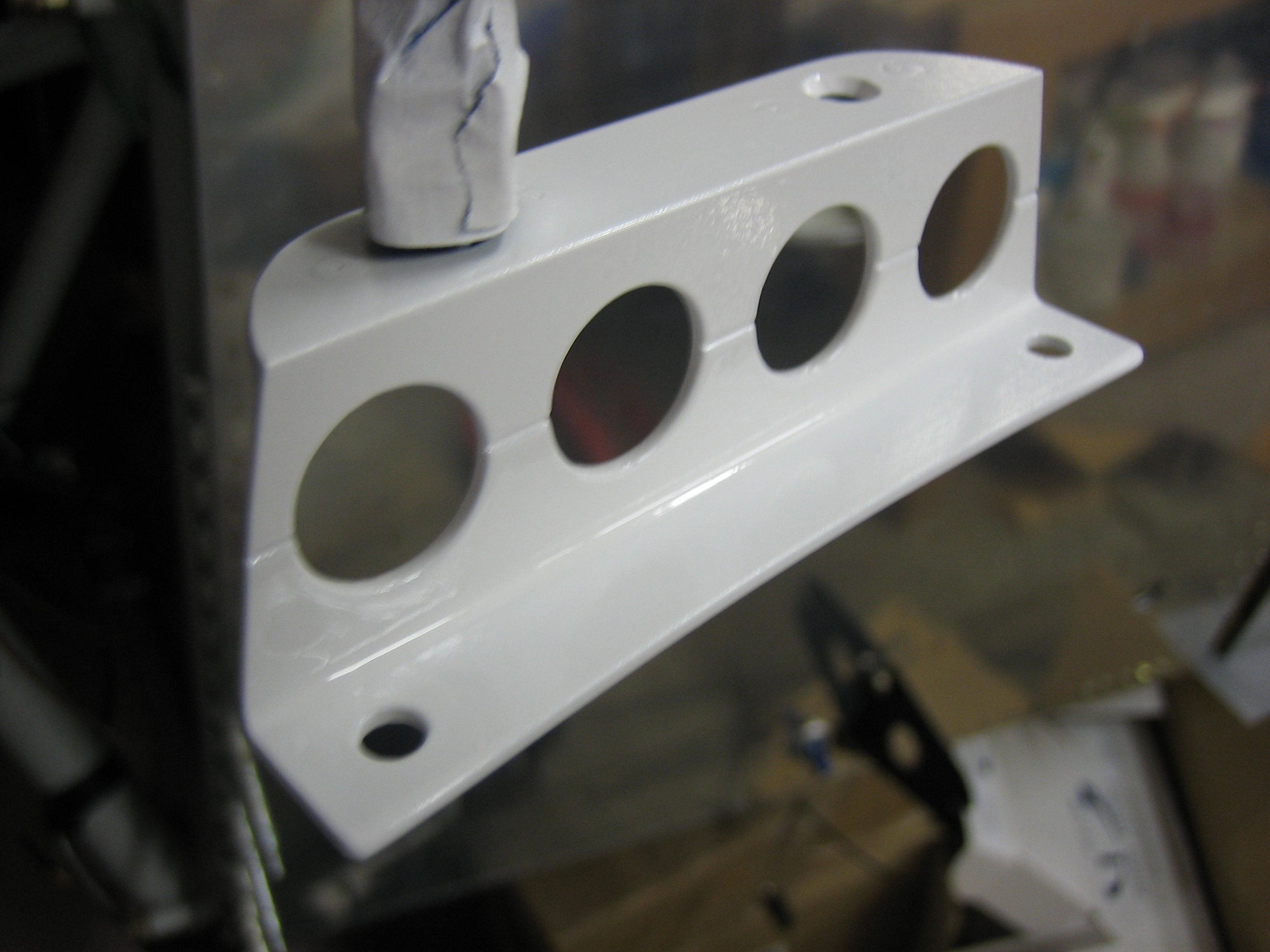
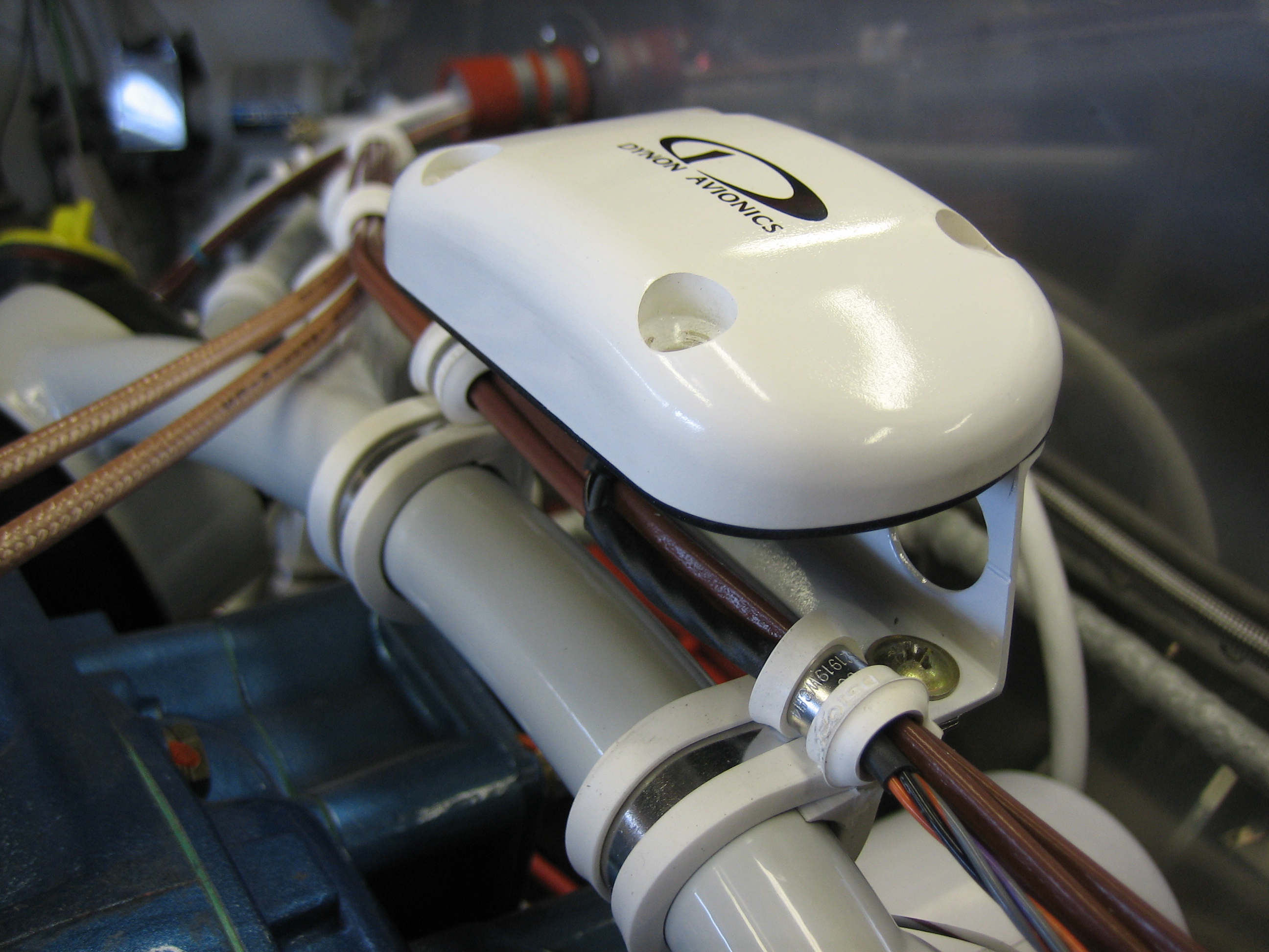
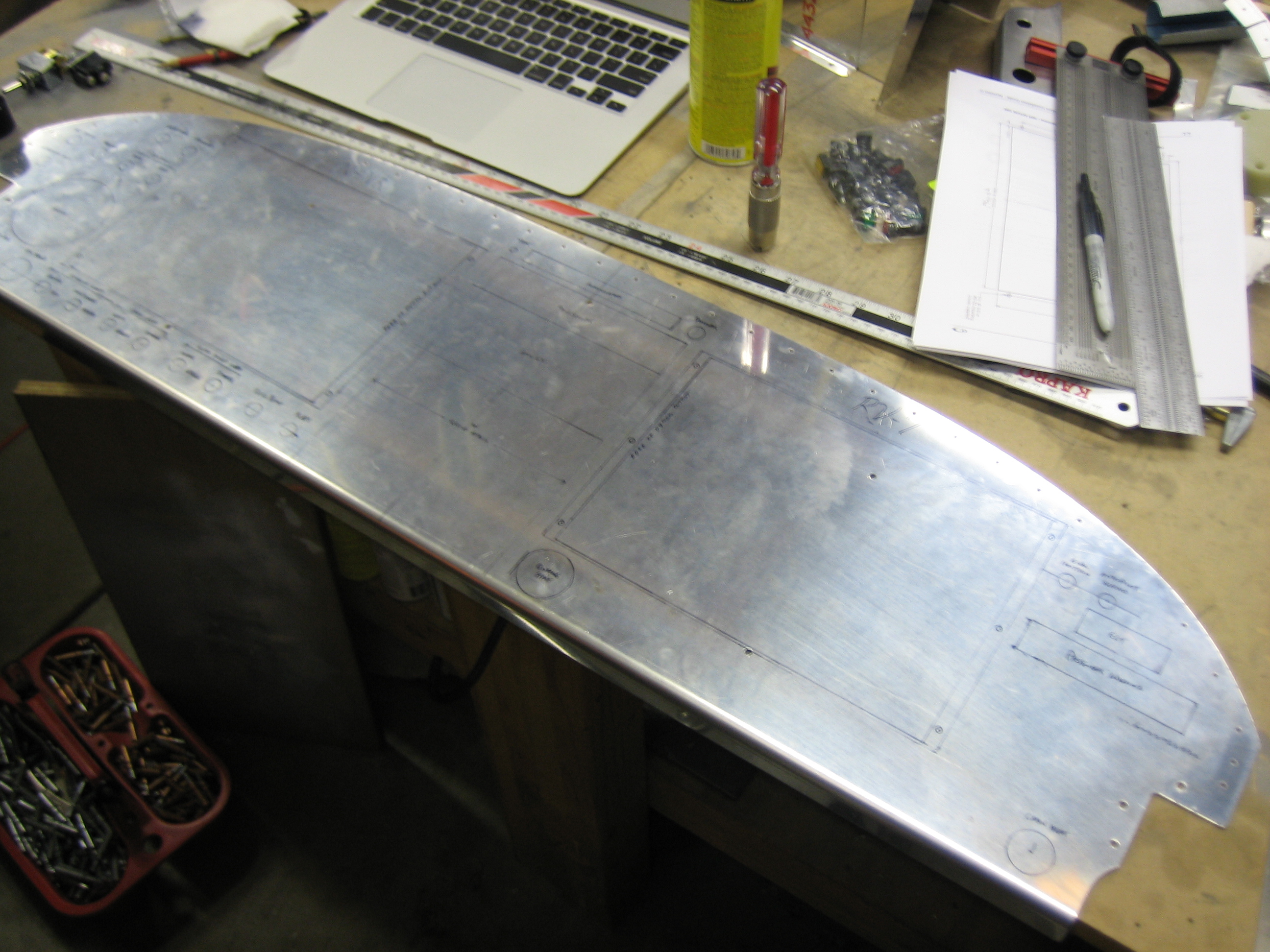
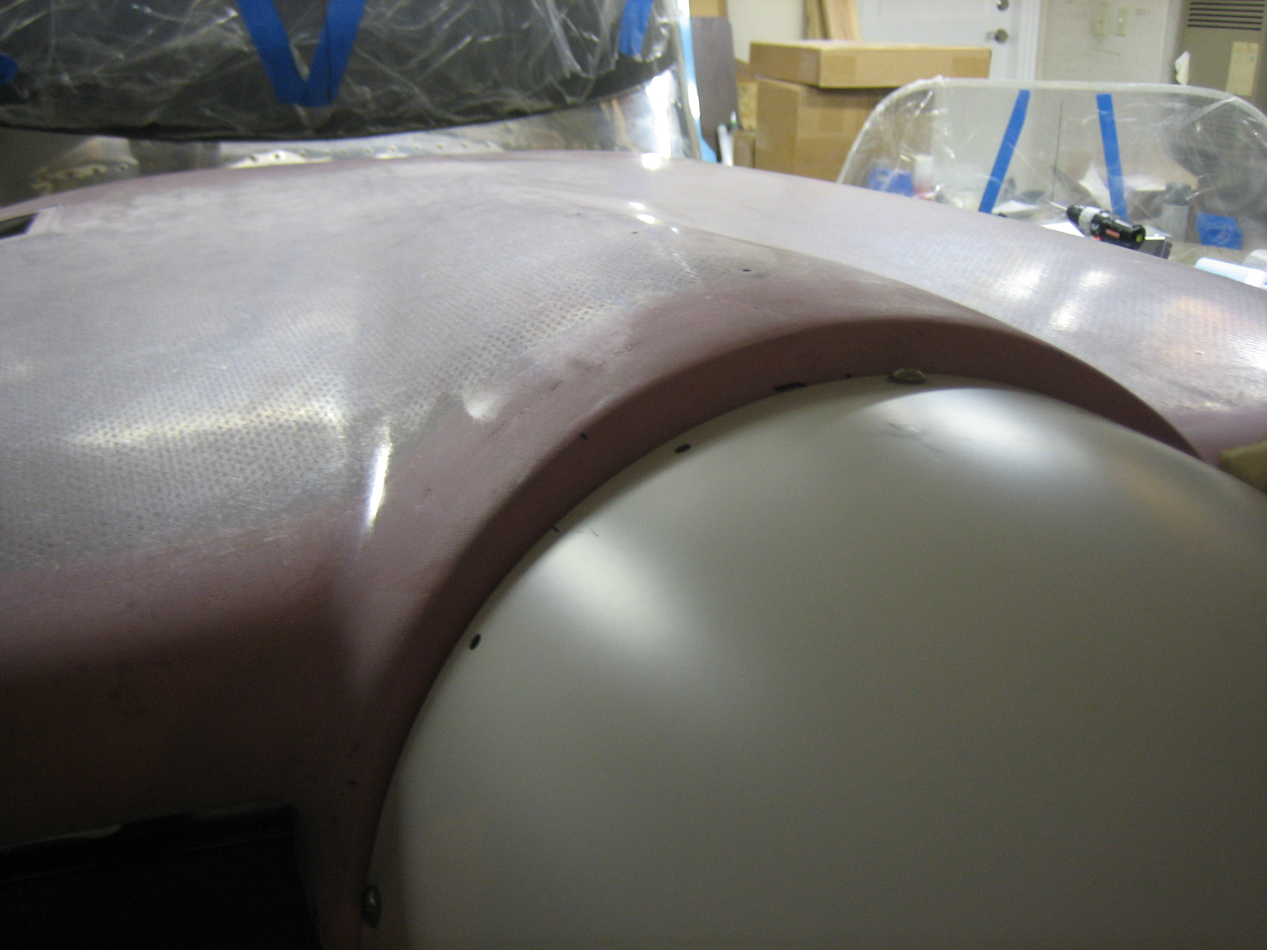
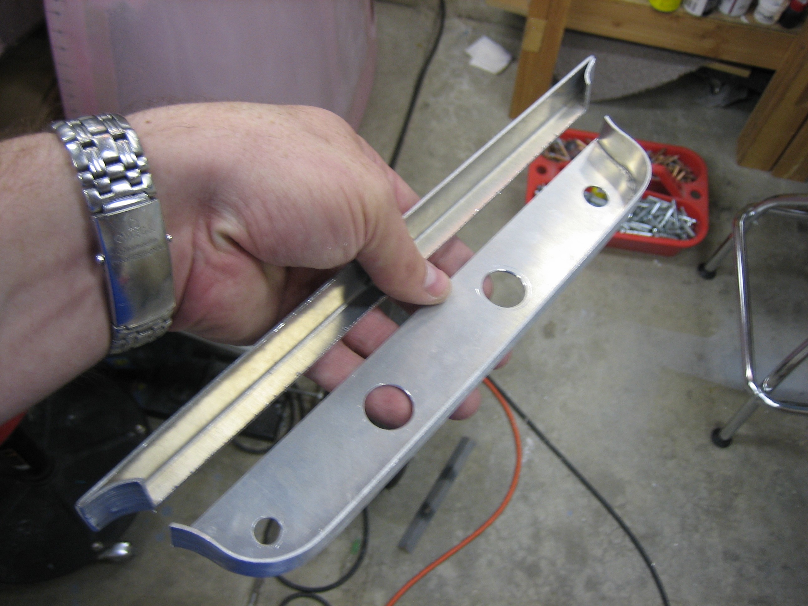
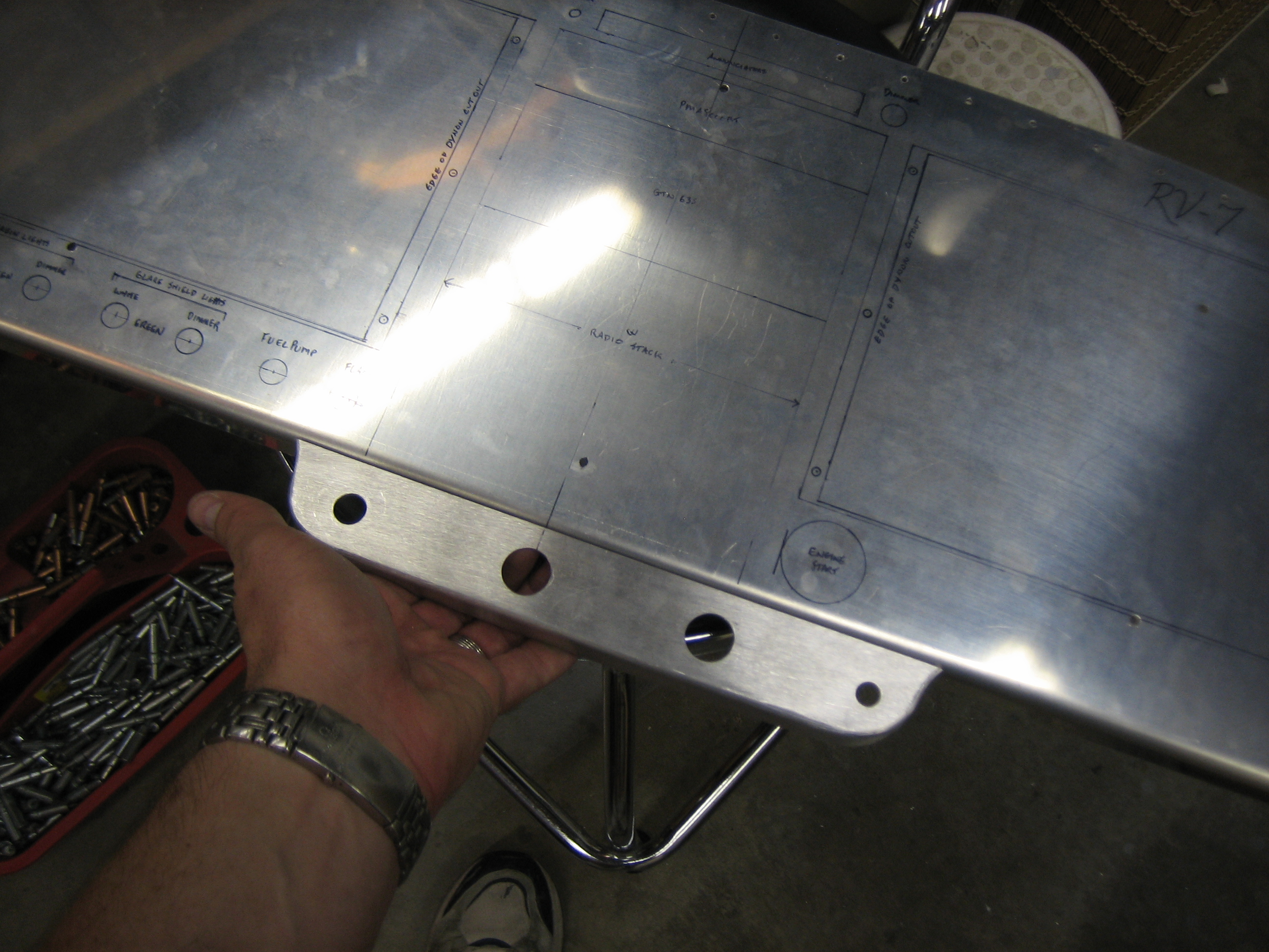
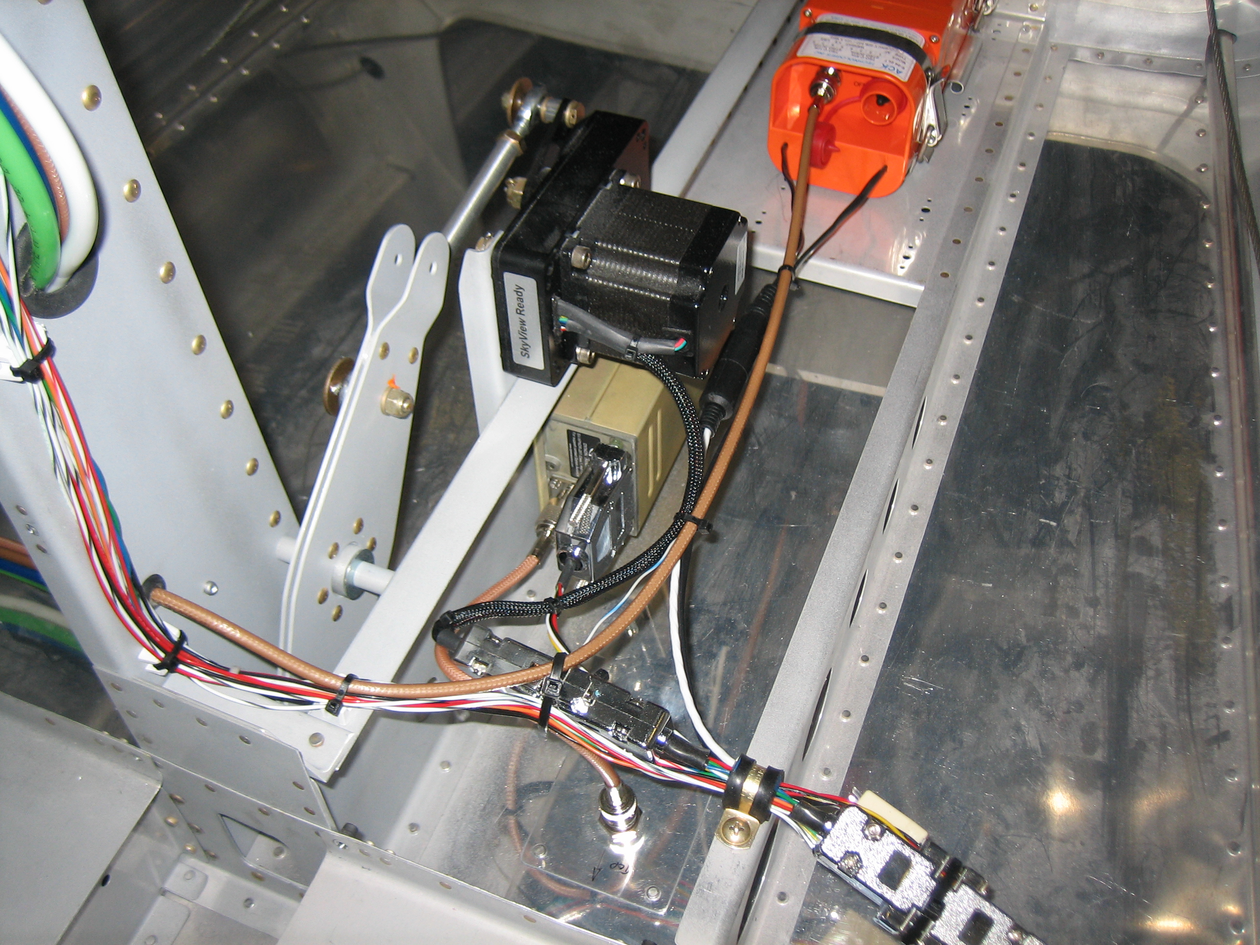
I also finished up the Dynon GPS mounting bracket. I put a gentle radius in the lower flange to follow the curve of the engine mount and drilled a few lightening holes. I then primed and painted it gloss white.