I got back from Oshkosh today. I had a few goals for the trip:
Audio Panel: I had been trying to decide between the Garmin GMA 240 and PS Engineering PMA5000EX. They’re both really nice units and each have their strengths and weaknesses. The PMA5000EX unit has the IntelliVox (auto-squelch) feature while the GMA 240 has the old style manual squelch control. However, the front panel controls on the GMA 240 are substantially more user-friendly and intuitive. I had been leaning pretty heavily towards the PMA5000EX, but after the show I’m more split. I still need to do some more research on this.
Canopy Attach: I have been trying to decide between screwing the canopy to the frame and gluing it on with sikaflex. The sikaflex solution results in no holes in the canopy which dramatically reduces the chance of cracks, but it’s still a relatively new solution, so the long-term success of this solution is not proven. The plans specify that the canopy is held on with screws all around, but the difference in the coefficients of expansion between aluminum and plexiglass is substantial, and a rigid fastener like a screw can put highly localized pressure on the canopy. After looking at a bunch of RVs parked in the parking area, I’ve decided that I’m going to use screws along the side skirts and around the aft edge of the rear window, but adhesive across the canopy and cabin frames. I saw one plane done like this and the results were outstanding.
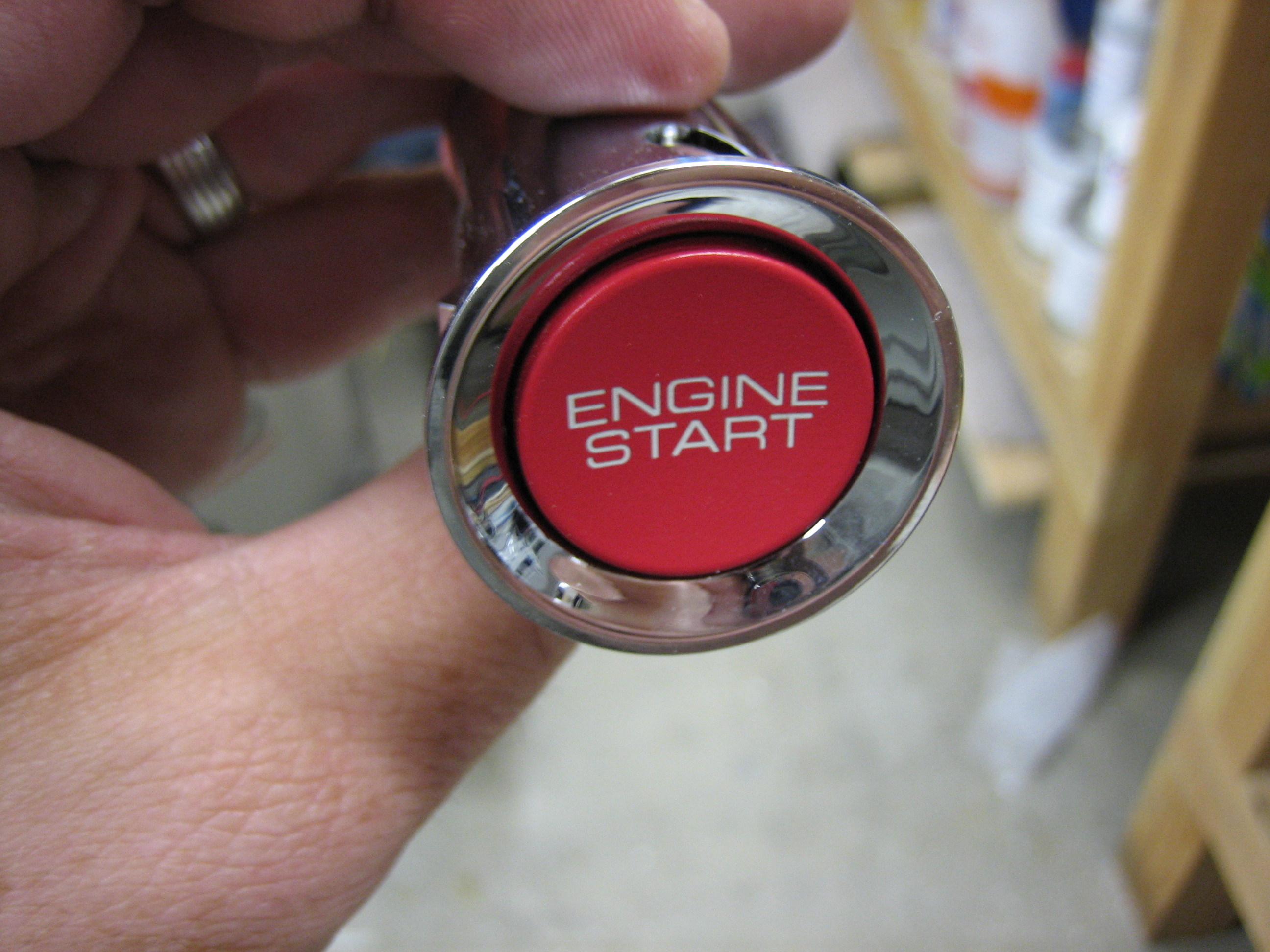
Electrical System: I’ve been planning on following the AeroElectric Connection wiring diagrams (Z-13), but recently Vertical Power announced the VP-X. This provides a solid state electrical system that is controlled through your EFIS. The only issue is that Dynon has not announced support for this since they’re still trying to finish the SkyView system. I think there is a high likelihood that they will provide support for it at some point though, so the question is whether it will happen by the time I need it. The VP-X provides some really nice features though such as start button disabling, landing/taxi light auto wig-wag, flap overspeed warning, flap positioning, flap extend disable above Vfe, auto trim speed adjustment based on airspeed, better fault detection and alerting, etc. If Dynon supported it with the SkyView, there is no question that I would go with it. I could gamble that it will be done by the time I need it, but then I could be grounded if it wasn’t. I also need to do some more research on this and see if I can put the decision off as long as possible.