I completed the same modification on the left flap hinge pin. No need to repeat the details, look back a few days if you want to see how I did this. This did take me about half the time the first one did though.

I completed the same modification on the left flap hinge pin. No need to repeat the details, look back a few days if you want to see how I did this. This did take me about half the time the first one did though.
I’ve been out sick the last couple of days, so I haven’t been able to do anything on the plane, but my order from Peterson Innovation showed up today. They make a slick little product called the Reservoir Dog that fits on your brake fluid reservoir to keep brake fluid from spilling out when you’re inverted. As you can see in the picture below, it fits between the aluminum reservoir and the breather cap that comes from Van’s. It contains a check valve that allows air into the reservoir when you’re upright, but seals tight when inverted.

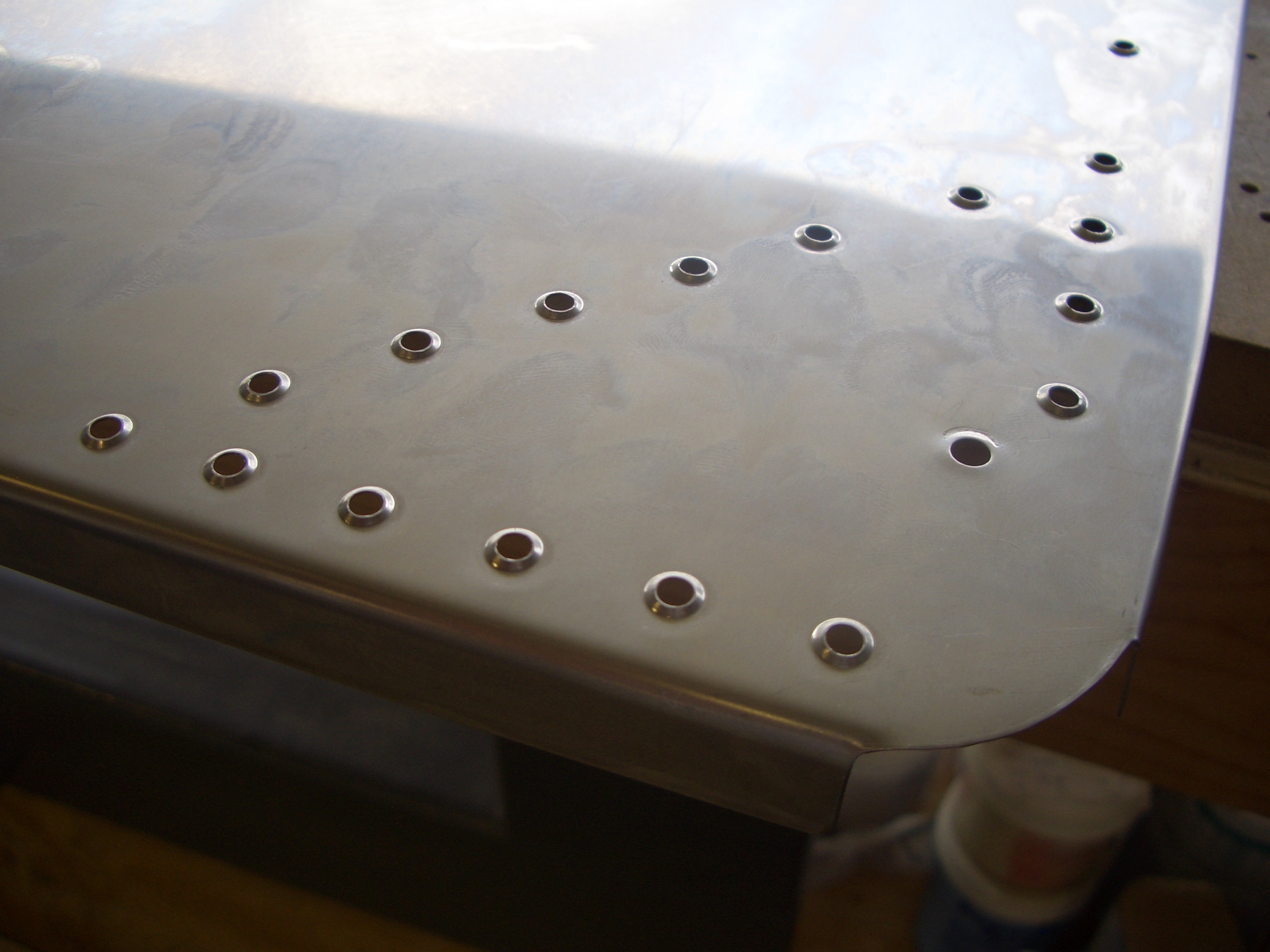
Now that I’m feeling better, I got started prepping the bottom wing skins for riveting. I deburred and dimpled two of the skins and installed the nutplates in three of the six cutouts. After the wing skins, I only have a small punch list of items to complete before I’m ready to rivet the bottom skins on:

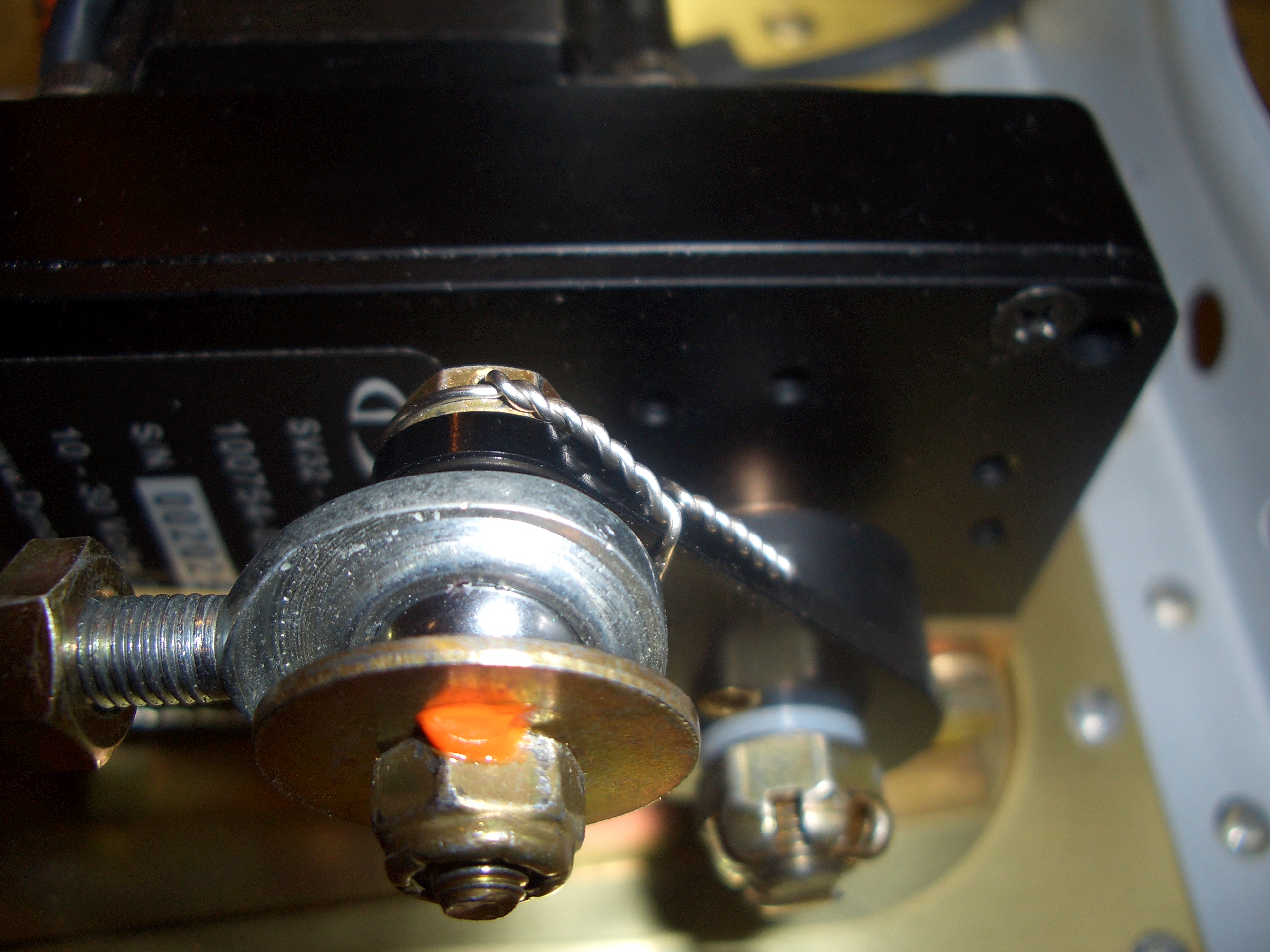
I safety wired the remaining two bolts on the autopilot roll servo. These are the bolts at either end of the short pushrod from the servo to the aileron bellcrank. These nuts as well as the remaining nuts in the aileron control linkage have been final torqued and torque sealed (orange lacquer). This is the bolt on the servo end of the pushrod.
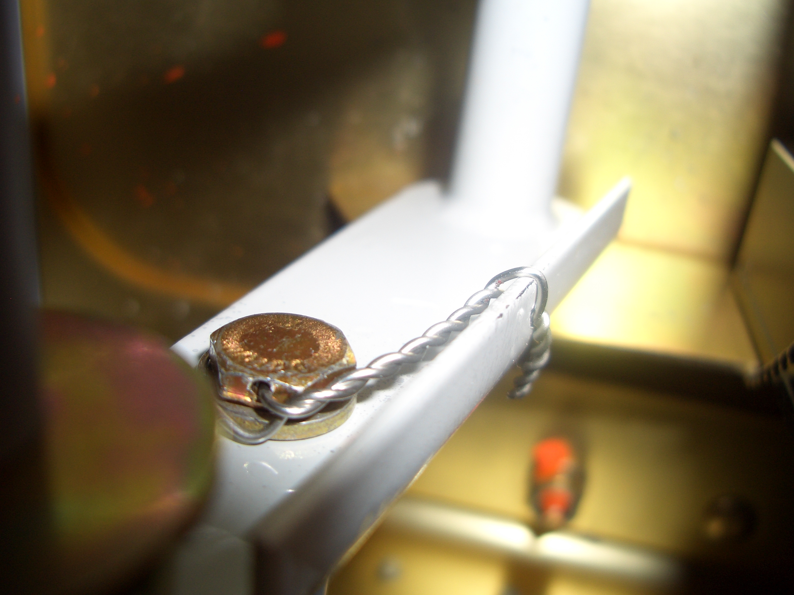
This is the bolt at the bellcrank end of the pushrod. I drilled a tiny #50 hole in the flange of the bellcrank to safety wire the bolt to.
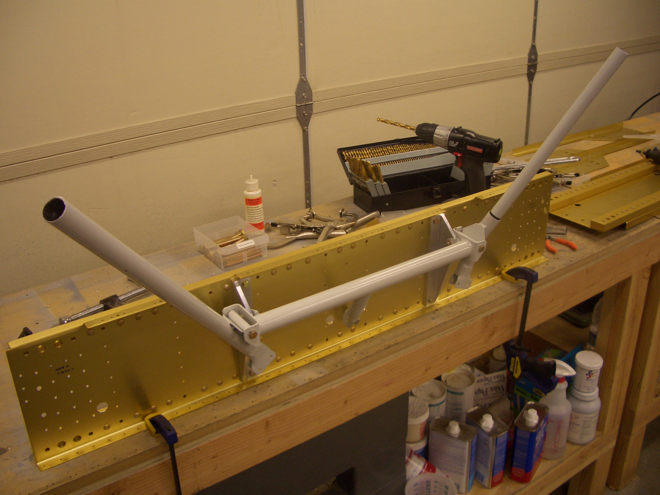
I fabricated a short piece of angle to tie the pitot tube mount to the adjacent wing rib. Positioning this required putting the pitot mount and bottom wing skin in place so that the piece of angle could be clamped to the rib. After removing the mount and bottom skin, the angle could be drilled to the rib.
Below the large push tube, you can see one of my experiments in keeping the pitot and AOA tubing away from the push tube. I’m not going with this arrangement, but I’ll post something in a few days about how I’m handling this.

Here it is with the mount back in place. This bit of angle adds considerable rigidity to the mount.

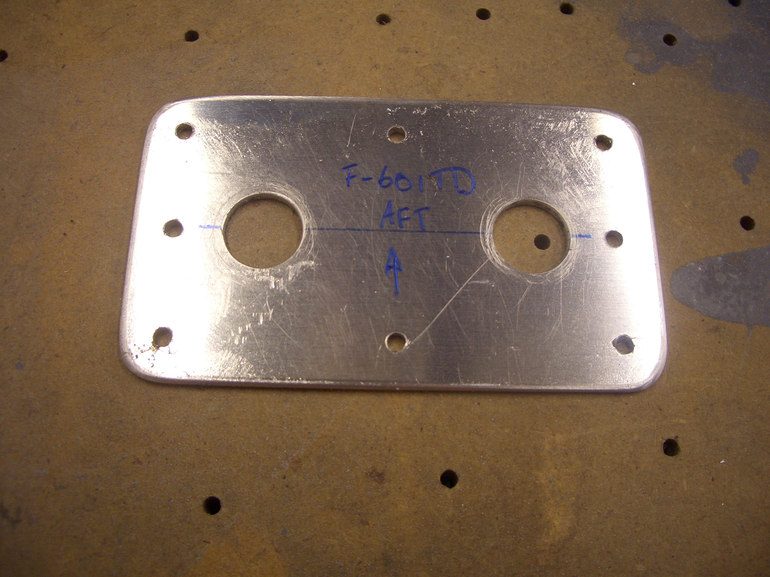
I fabricated the F-601TD brake reinforcement doubler and match drilled it to the fuselage. I also laid out and drilled the 7/16″ holes through this and the firewall. Drilling stainless is pretty hard on cutting tools, but I used some foam that is a tapping lubricant and that seemed to work really well.
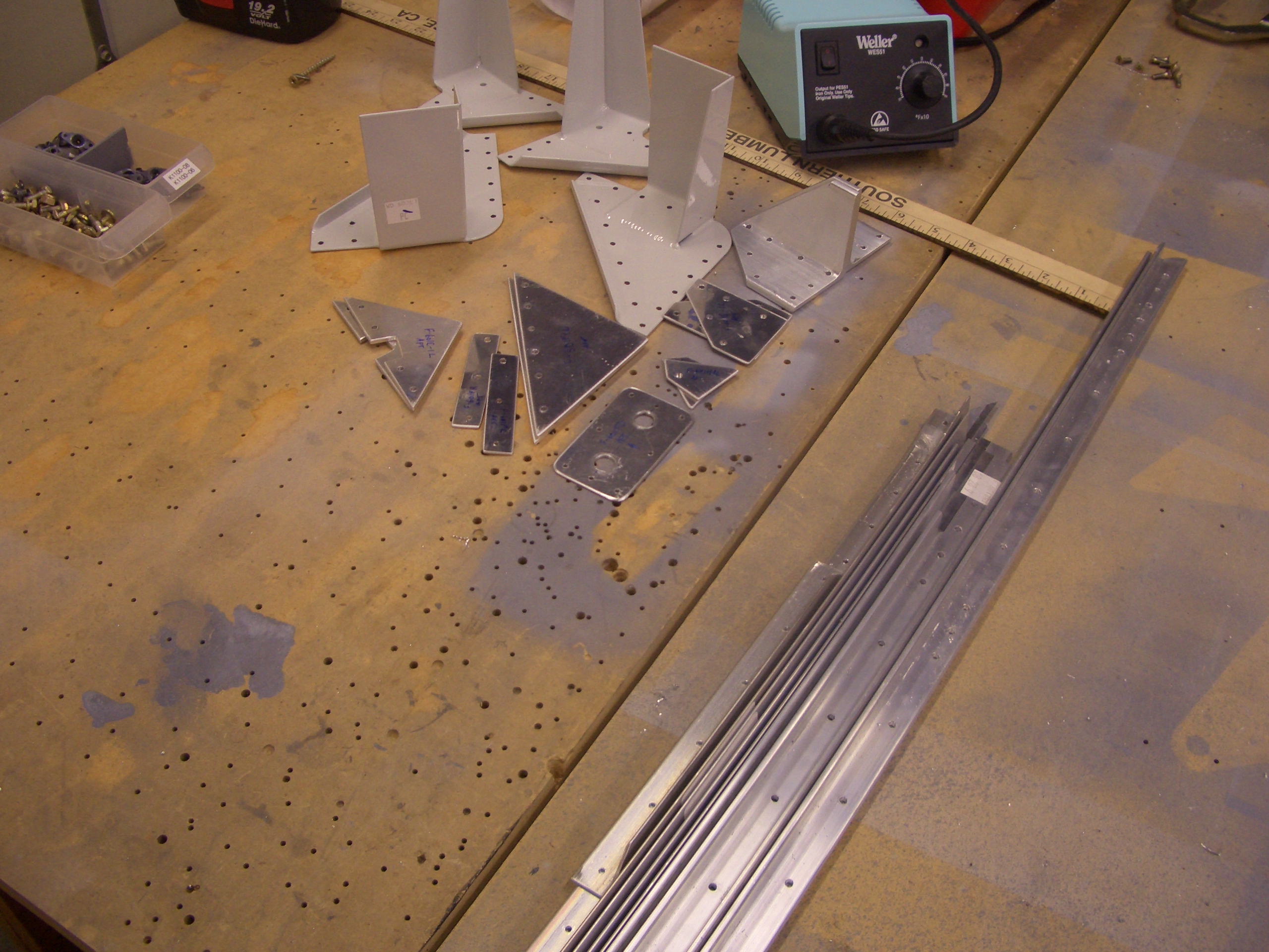
Here are all of the components that came off of the firewall. I deburred all of these except for the steel brackets at the top. There’s still a lot of work to do here as the firewall side of most of these pieces needs to be machine countersunk to receive the dimples in the firewall.
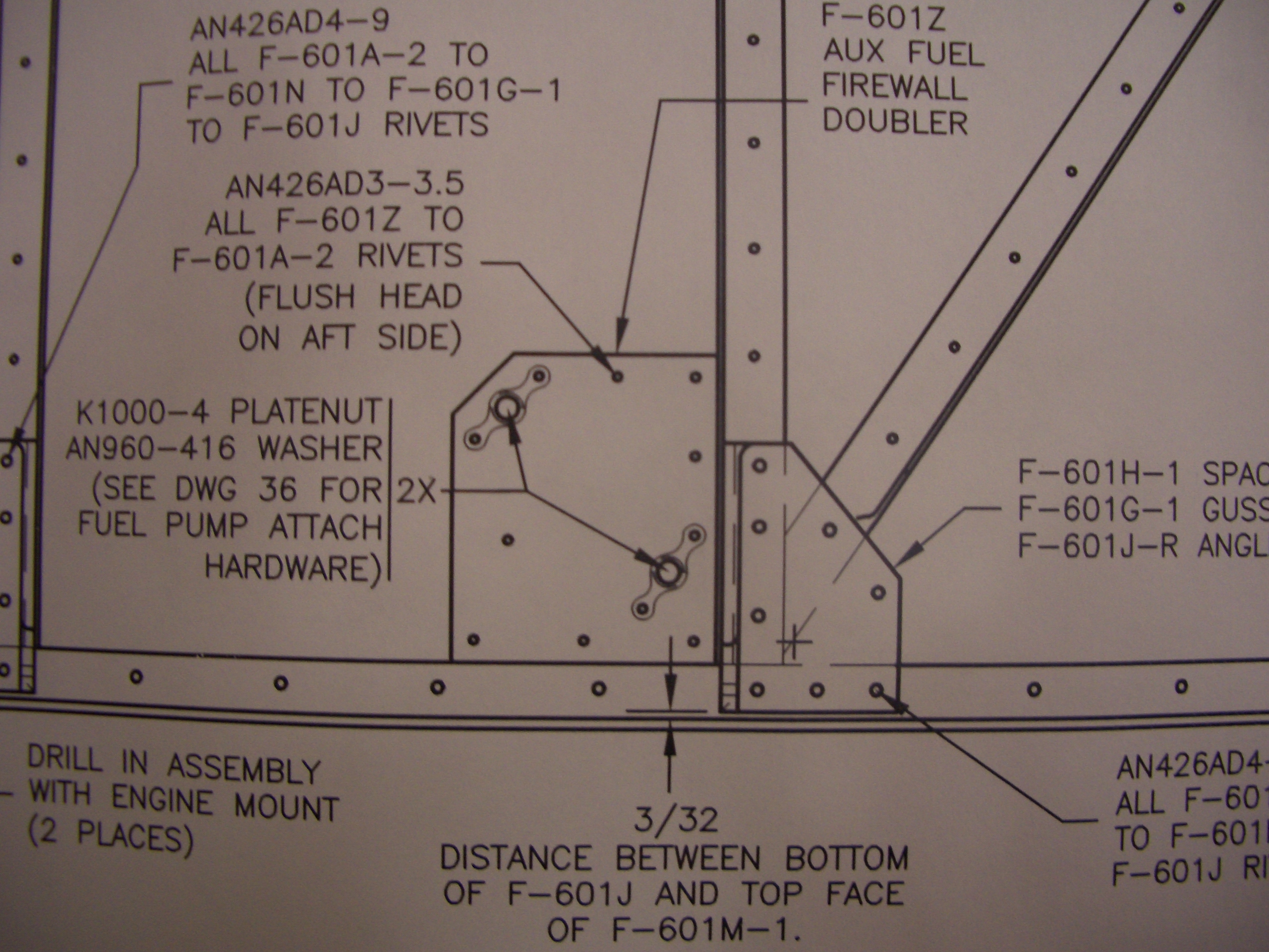
The plans don’t make any mention of it, but the F-601Z aux fuel firewall doubler isn’t required if you’re using a fuel injected engine as I will be. Leaving this out means a lot fewer unnecessary holes in the firewall.
My mom is in town, so I got her help dimpling the firewall. I was a little worried that the DRDT-2 dimpler wouldn’t make as crisp of a dimple in the stainless (though I didn’t even try to see if this fear was warranted). My buddy Andre has a couple of the traditional Avery style dimplers, so I borrowed one to dimple the firewall.
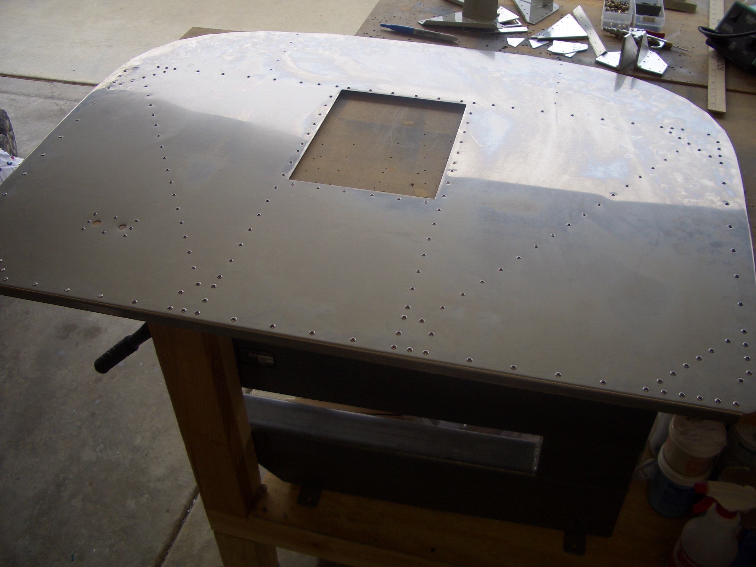
My step-father Curtis was in town and gave me a hand prepping the firewall components for priming and helped me back-rivet everything in place. We had a little problem with one of the corners because the firewall wasn’t sitting flat on the back rivet plate. I drilled the problem rivets out though and everything looks great now. Like many other builders, I had to go up in length on some of the rivets to get a sufficiently large shop head (though I don’t think it would have mattered to just use the size called out for in the plans).
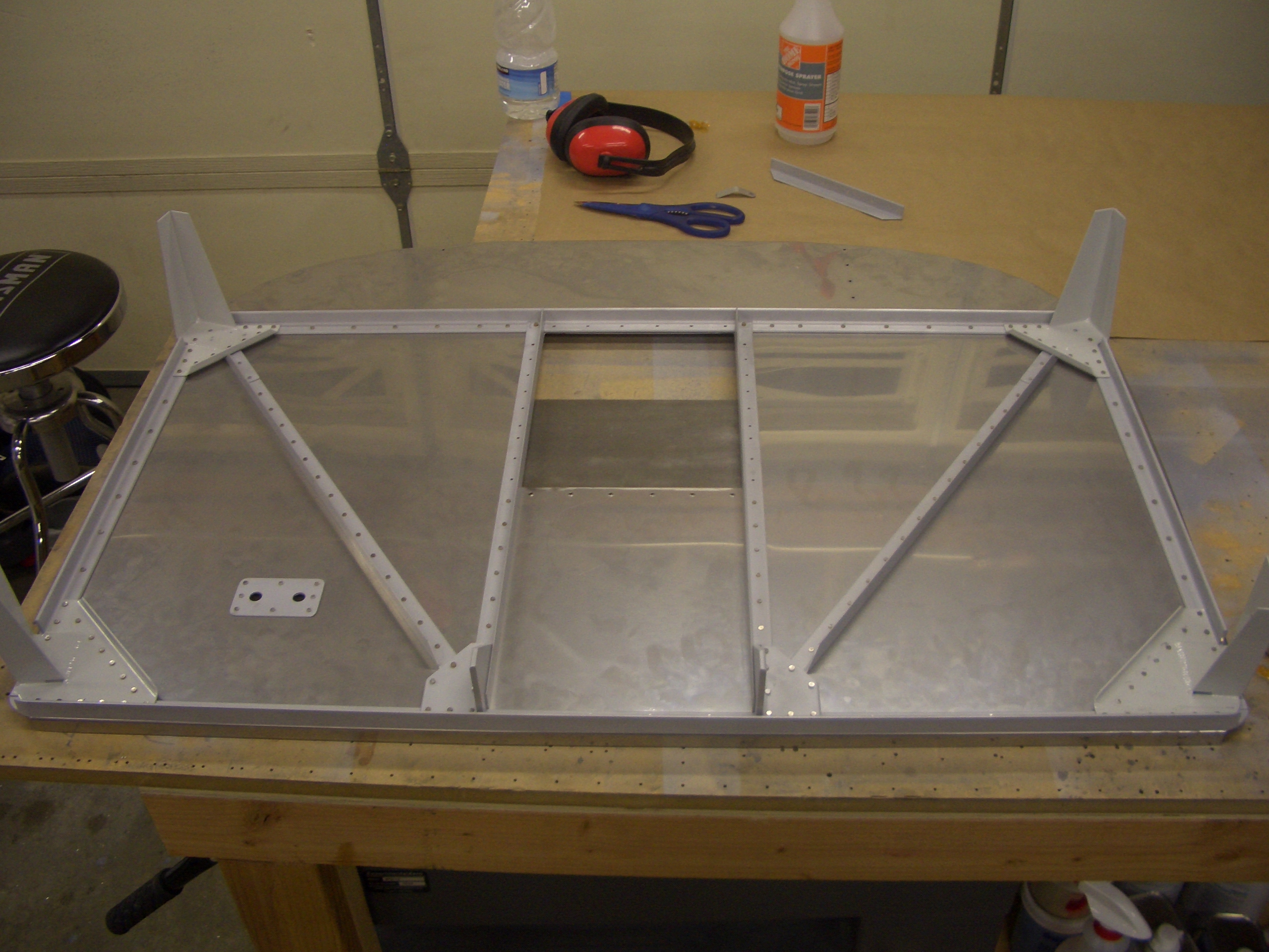
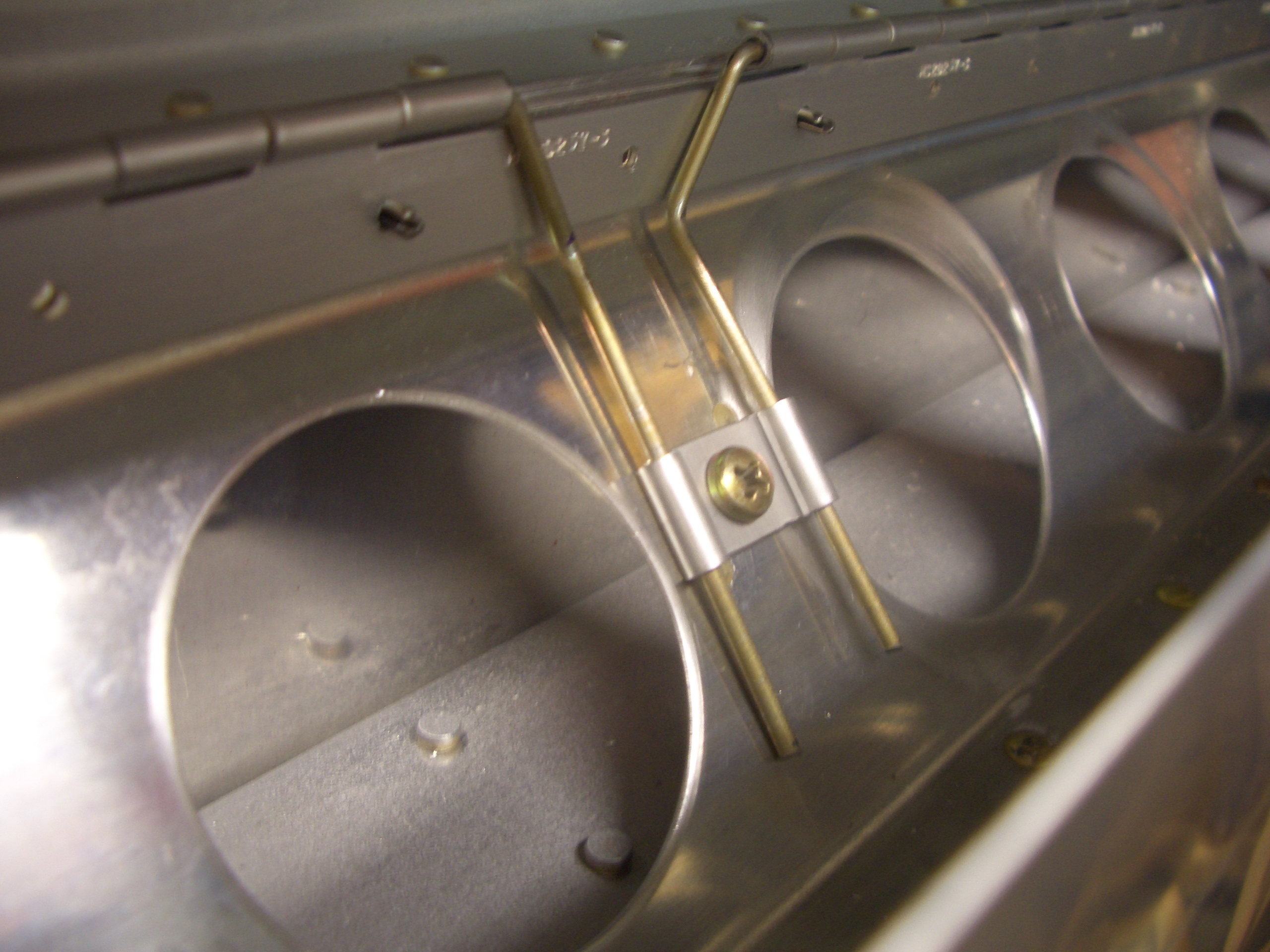
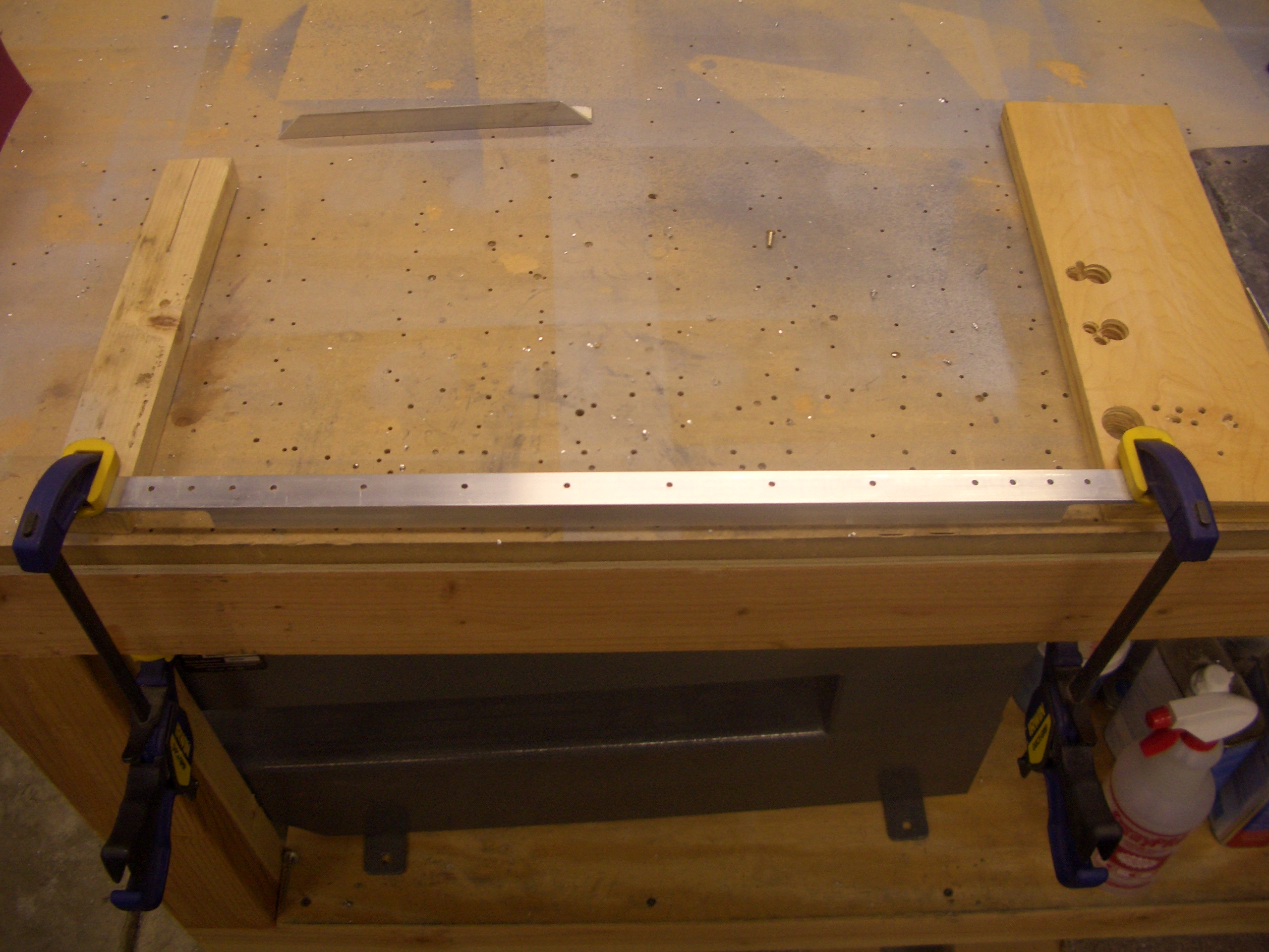
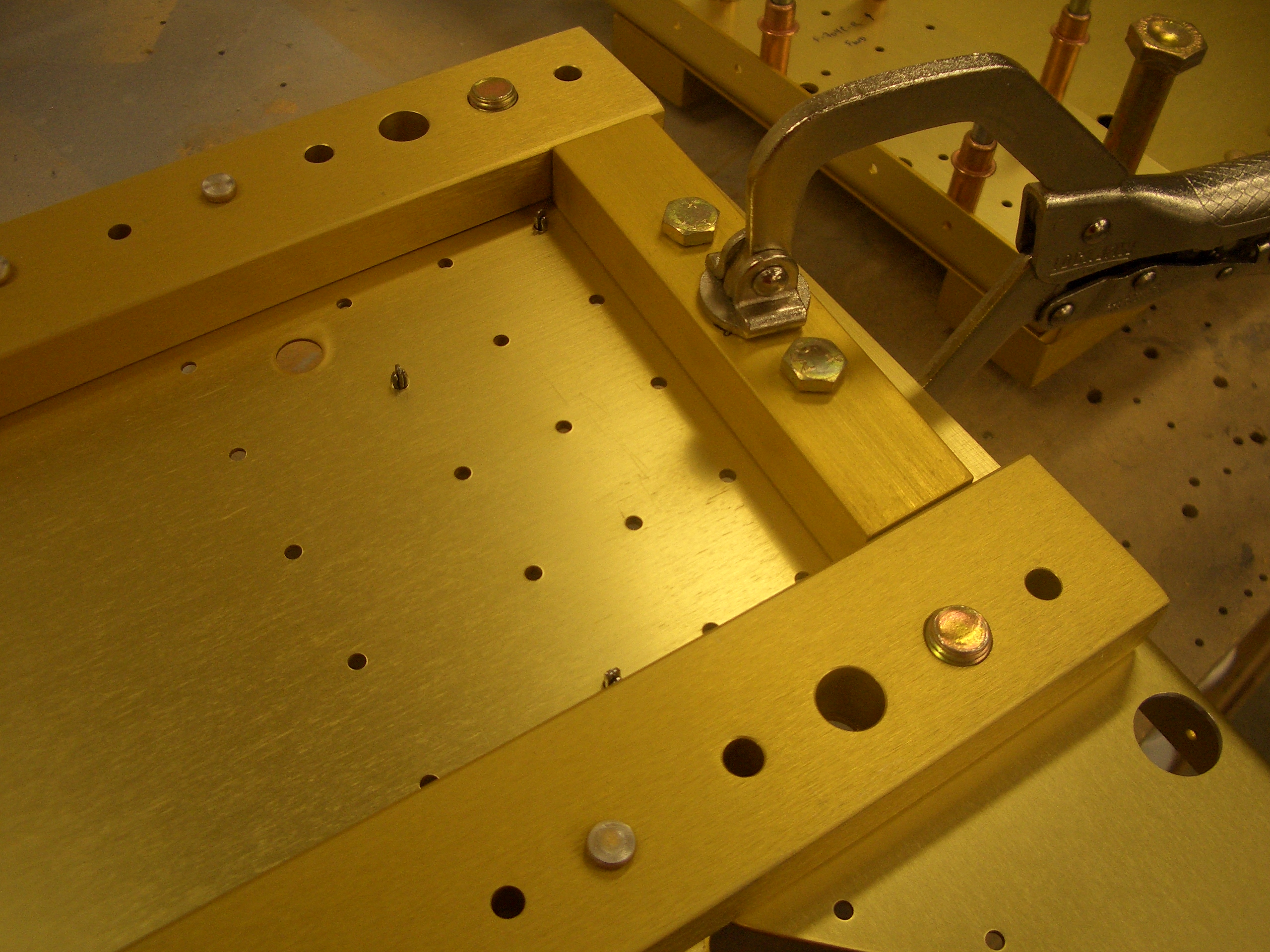
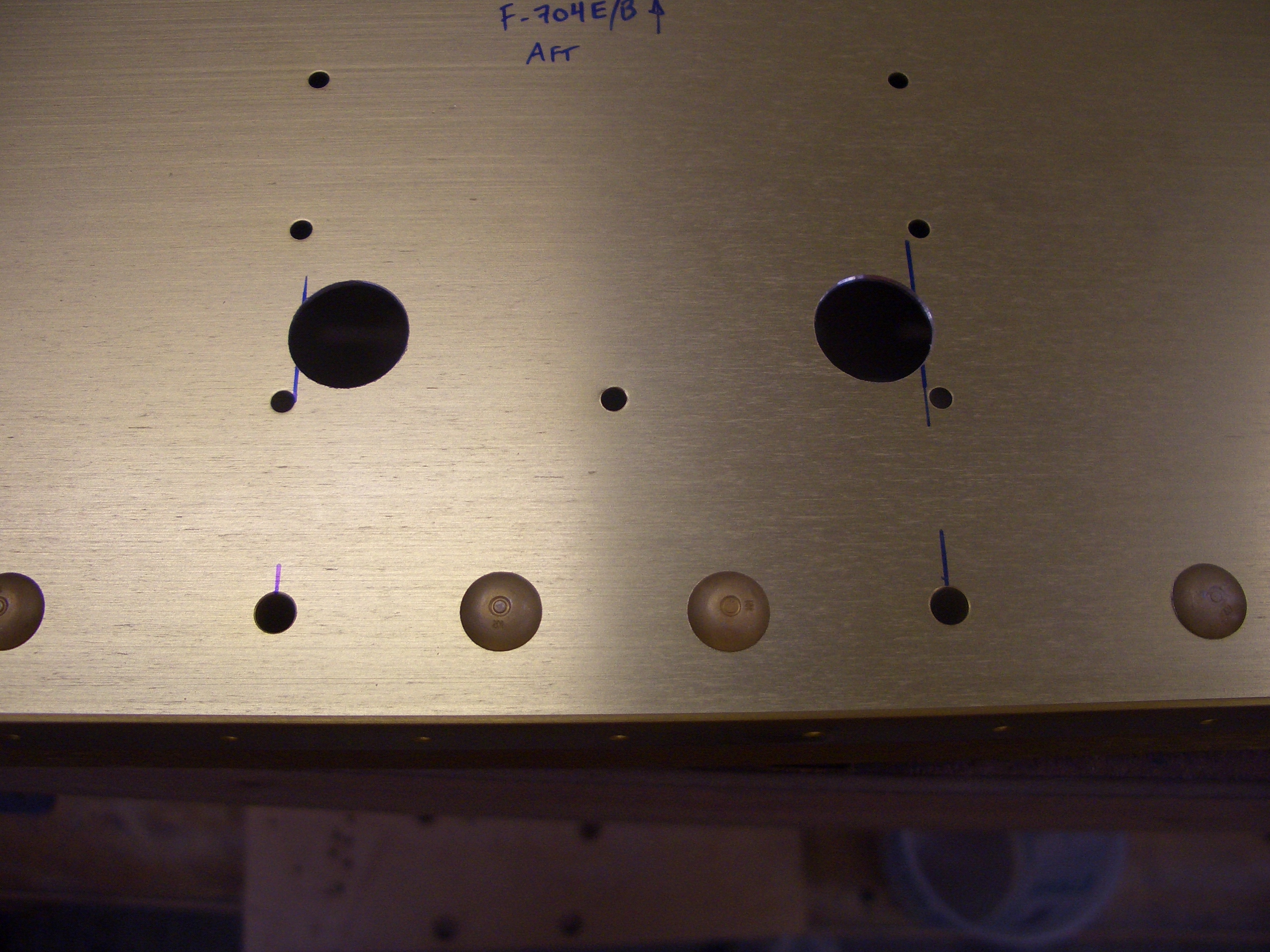
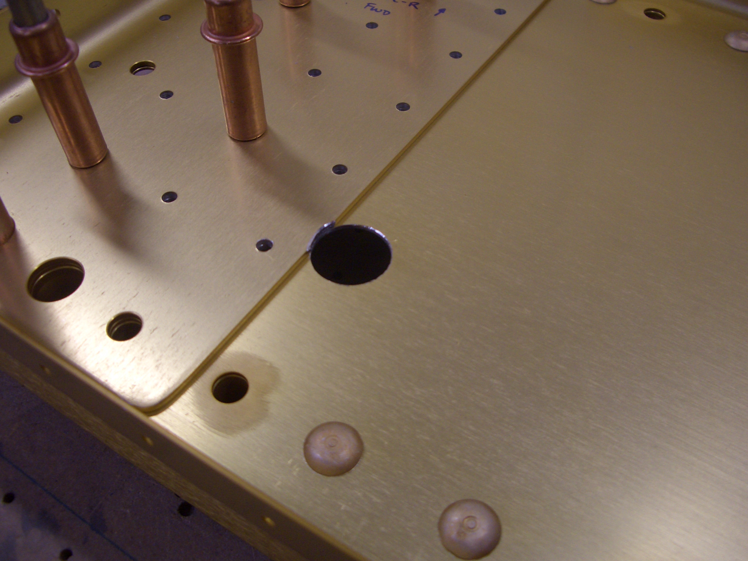
Now that the firewall is out of the way, I got started on the center section. First up is to enlarge the holes in the side supports to allow the rudder cables to pass through. These are drilled out to 5/8″ for an SB625-7 snap bushing.
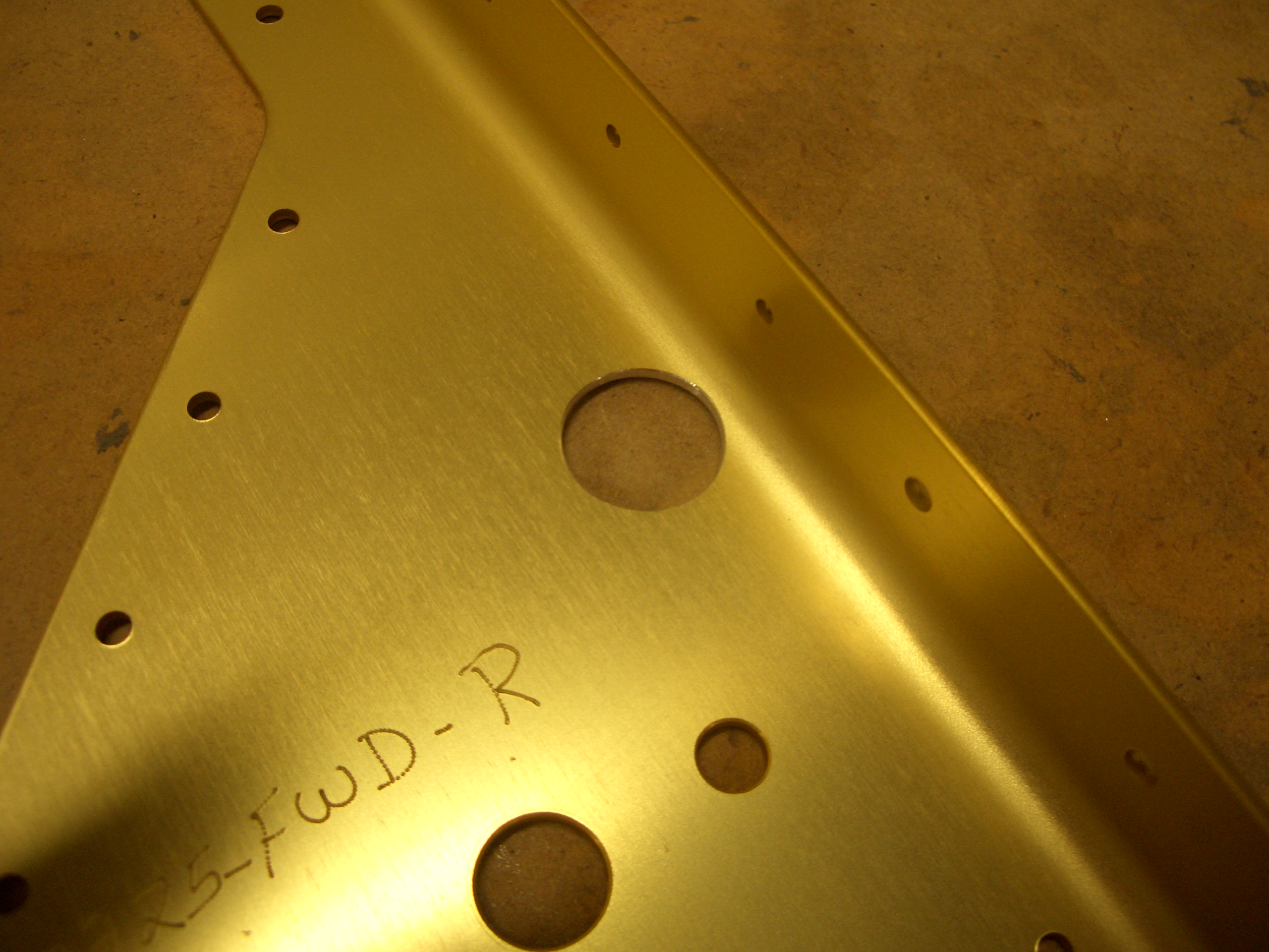
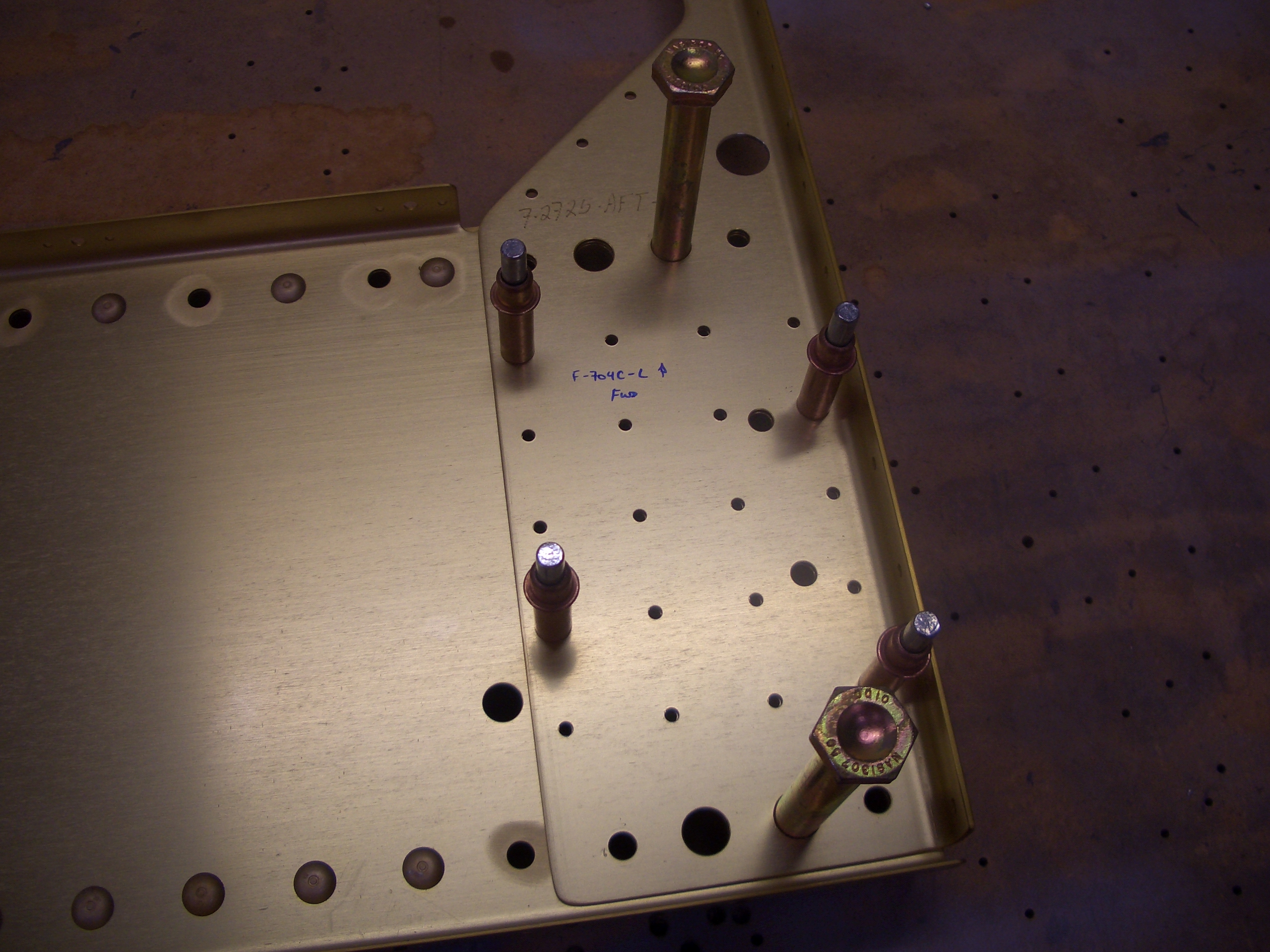
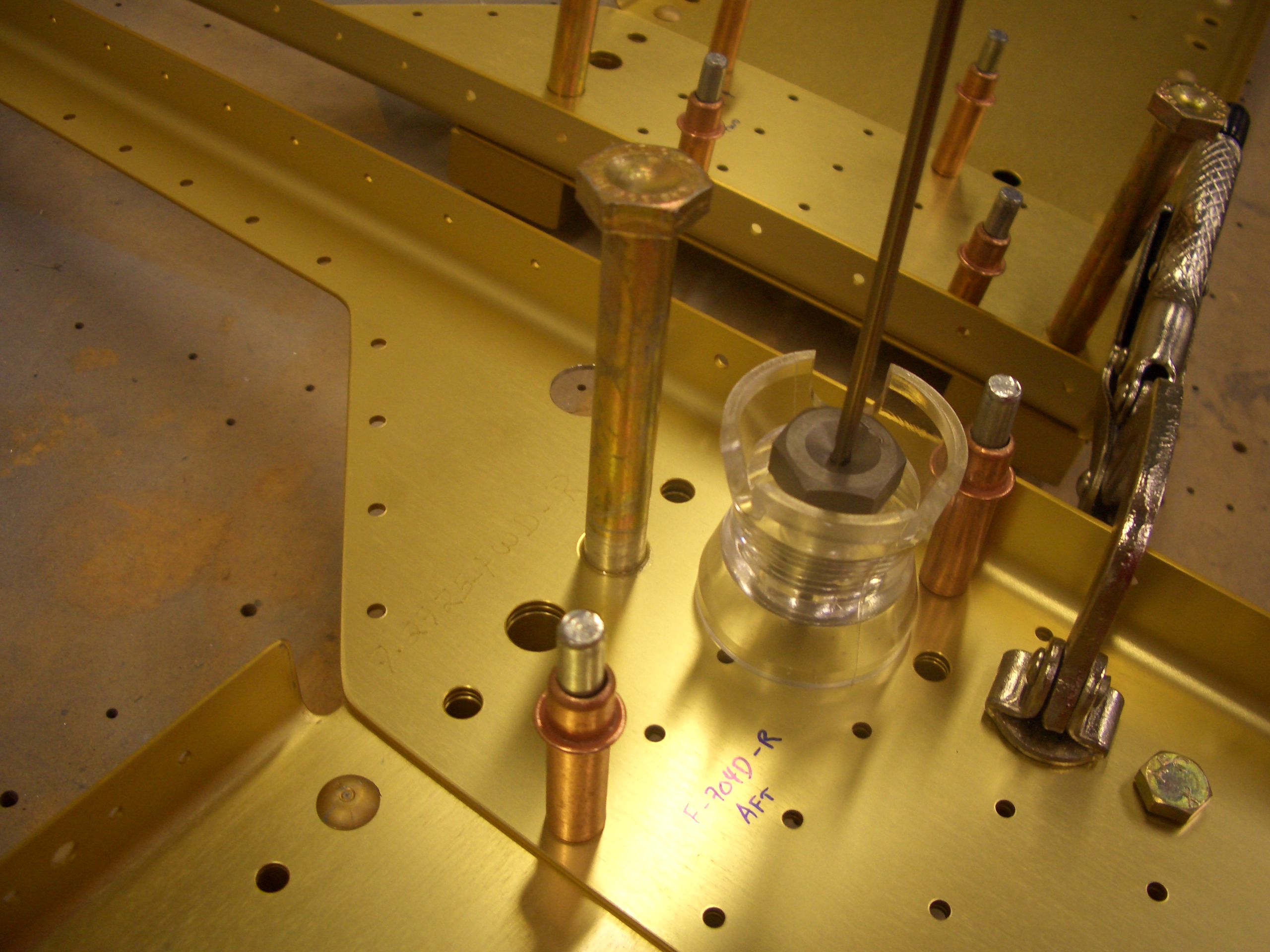
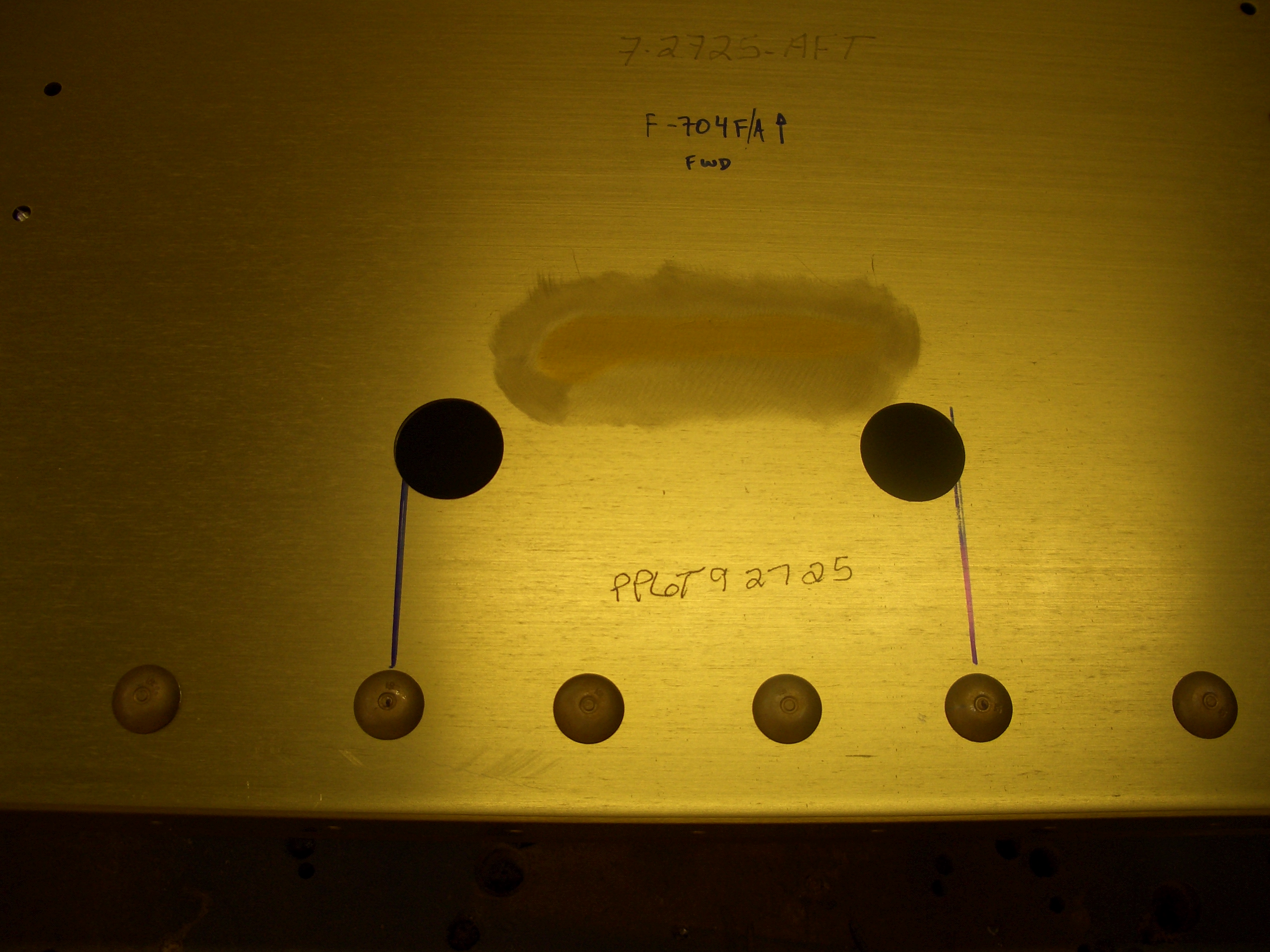
I also noticed something odd when laying out all of the pieces. Van’s apparently mismarked the forward and after center sections (the aft section was marked fwd and vice versa). This may have just been a marking error, but if the center section was flipped end for end when the wing spars were match drilled, then the close tolerance bolt holes may not line up precisely when the wings are mated. I’ll call Van’s on Monday to see if they think this is an issue. Hopefully their drilling jig won’t let this sort of mistake happen.
Update: I spoke with Ken at Van’s and he’s about 99% sure this is simply a marking mistake. He didn’t know if their drilling jig would let them drill the center section backward, but said that if I wanted to be 100% sure, I could simply install the center section onto each wing using the close tolerance bolts to see if the holes lined up.
I fabricated the control stick bushings and mounted the control sticks tonight. I’m still not happy with these though. The pilot’s side stick has a little bit of play between the stick and the bushing, and the passenger side is binding a little bit. It’s late though, so I’ll work on these more tomorrow.